Adaptive cruise control:
- Adaptive Cruise Control (ACC) is an automotive feature that allows a vehicle's cruise control system to adapt the vehicle's speed to the traffic environment.
- Mitsubishi was the first to offer a lidar-based distance detection system on the Japanese market in 1992. Marketed as "Distance Warning", this early system warns the driver, without influencing throttle, brakes or gearshifting.
- A radar or Lidar system attached to the front of the vehicle is used to detect whether slower moving vehicles are in the ACC vehicle's path. If a slower moving vehicle is detected, the ACC system will slow down the vehicle and control the clearance, or time gap, between the ACC vehicle and the forward vehicle.The LiDAR system can readily detect objects located in the range of 30 meters to 200 meters.
- If the system detects that the forward vehicle is no longer in the ACC vehicle's path, the ACC system will accelerate the vehicle back to its set cruise control speed. This operation allows the ACC vehicle to autonomously slow down and speed up with traffic without intervention from the driver.
- The method by which the ACC vehicle's speed is controlled is via engine throttle control and limited brake operation.


ACC
Sensor – It consists of a single sensor with a
seven-beam antenna and multichannel RF transceiver Two “general” short-range beams look to
the left and right of the vehicle (GL and GR); at
a medium range, far right and far left
beam widths of 12 degrees focus on the cut-in region (LL and RR), and the three 4-degree beams are employed
for long range forward target acquisition and tracking (L,C, R). The total
coverage area is +/− 20 degrees.
ACC Module – The primary function of the ACC module is to process the radar information and determine if a forward vehicle is present. When the ACC system is in 'time gap control', it sends information to the Engine Control and Brake Control modules to control the clearance between the ACC Vehicle and the Target Vehicle.
Engine Control Module – The primary function of the Engine Control Module is to receive
information from the ACC module and Instrument Cluster and control the vehicle's speed based on this information. The Engine Control Module controls vehicle speed by controlling the engine's throttle.
Brake Control Module – The primary function of the Brake Control Module is to determine
vehicle speed via each wheel and to decelerate the vehicle by applying the brakes when
requested by the ACC Module. The braking system is hydraulic with electronic enhancement, such as an ABS brake system.
Instrument Cluster – The primary function of the Instrument Cluster is to process the Cruise Switches and send their information to the ACC and Engine Control Modules. The Instrument Cluster also displays text messages and telltales for the driver so that the driver has information regarding the state of the ACC system.
CAN – The Controller Area Network (CAN) is an automotive standard network that utilizes a 2 wire bus to transmit and receive data.
Cruise Switches – The Cruise Switches are mounted on the steering wheel and have several buttons which allow the driver to command operation of the ACC system.


Electronic Transmission Control system
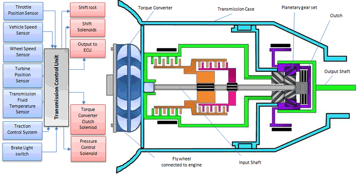
The Transmission Control Module (TCM) controls modern automotive transmissions based on input from various sensors as well as data provided by engine control module (ECM). It processes this input to calculate how and when to shift gears in the transmission and generates the signals that drive actuators to accomplish this shifting. The software in the TCM is designed to optimize vehicle performance, shift quality and fuel economy.
Electronic sensors monitor the gear position selection, vehicle speed, throttle position and a number of other parameters. Based on this information, the control module adjusts the current supplied to solenoids in the transmission that control the position of various valves and gears.
The gear position selector switch communicates to the TCM which gear has been selected by the operator. The crankshaft position sensor provides information to the TCM to determine the existing rotational speed of the engine. This information helps the TCM determine when to change gears. The throttle position sensor tells the TCM how far the throttle is open which indirectly indicates the engine load. This input is used to determine the best time to change a gear. The turbine speed sensor determines the speed of the torque converter. The TCM uses this information to find the slippage across the torque converter, which helps it decide when to activate the torque converter lock-up clutch. The torque converter lock-up clutch(mechanically connects the impeller and turbine when the lock up clutch is engaged) increases the efficiency of the transmission by eliminating the hydraulic and pumping losses associated with the torque converter when traveling at steady high speeds. The transmission fluid temperature sensor is used to ensure that the automatic transmission fluid is at the correct temperature. If the automatic transmission fluid is hot, then the transmission is downshifted. The brake pedal position sensor helps to ensure that the driver has applied the brake before shifting into park or reverse. The TCM may also downshift the transmission if the vehicle is going downhill in order to utilize the compression braking(the Exhaust Valve is partially opened just before Top dead centre of the Compression stroke of each piston and this bleeds out the compressed air and so instead of a “Power Stroke” following the compression stroke there is a “Vacuum Stroke” and it is this change in the cycle that provides the “Braking Force”) of the engine. Inputs from the traction control system instruct the transmission to downshift when one or more tires are losing traction.
Actuators
Solenoid Actuated Valves: Powered by relays at TCM. Pressure Regulating Solenoids: Force Motor Solenoids, Variable Bleed Solenoids. Shift Solenoids: Electrical solenoids which are activated to change gears. Torque Converter Clutch Solenoids: Lock up stock style, Non lock up style.


There is a speed sensor on all four wheels and a separate valve for all four wheels. With this setup, the controller monitors each wheel individually to make sure it is achieving maximum braking force.
Three-channel, four-sensor ABS
There is a speed sensor on all four wheels and a separate valve for each of the front wheels, but only one valve for both of the rear wheels. Older vehicles with four-wheel ABS usually use this type.
Three-channel, three-sensor ABS
This scheme, commonly found on pickup trucks with four-wheel ABS, has a speed sensor and a valve for each of the front wheels, with one valve and one sensor for both rear wheels. The speed sensor for the rear wheels is located in the rear axle. This system provides individual control of the front wheels, so they can both achieve maximum braking force.
Two-channel, four sensor ABS
This system, commonly found on passenger cars from the late '80s through early 2000s uses a speed sensor at each wheel, with one control valve each for the front and rear wheels as a pair.
One-channel, one-sensor ABS
This system is commonly found on pickup trucks with rear-wheel ABS. It has one valve, which controls both rear wheels, and one speed sensor, located in the rear axle. This system operates the same as the rear end of a three-channel system. The rear wheels are monitored together and they both have to start to lock up before the ABS kicks in.
Electronic Transmission Control system
A transmission control unit or TCU is a device that controls modern electronic automatic transmissions. A TCU generally uses sensors from the vehicle as well as data provided by the engine control unit (ECU) to calculate how and when to change gears in the vehicle for optimum performance, fuel economy and shift quality.
Electronically controlled transmissions, which uses hydraulics to actuate the clutches and bands, but each hydraulic circuit is controlled by an electric solenoid. This simplifies the plumbing on the transmission and allows for more advanced control schemes Electronically controlled transmissions have even more elaborate control schemes. In addition to monitoring vehicle speed and throttle position, the transmission controller can monitor the engine speed, if the brake pedal is being pressed, and even the anti-lock braking system.
Using this information and an advanced control strategy based on fuzzy logic -- a method of programming the control systems using human-type reasoning -- electronically controlled transmissions can do things like:
- Downshift automatically when going downhill to control speed and reduce wear on the brakes.
- Upshift when braking on a slippery surface to reduce the braking torque applied by the engine.
- Inhibit the upshift when going into a turn on a winding road.
Electronic sensors monitor the gear position selection, vehicle speed, throttle position and a number of other parameters. Based on this information, the control module adjusts the current supplied to solenoids in the transmission that control the position of various valves and gears.
The gear position selector switch communicates to the TCM which gear has been selected by the operator. The crankshaft position sensor provides information to the TCM to determine the existing rotational speed of the engine. This information helps the TCM determine when to change gears. The throttle position sensor tells the TCM how far the throttle is open which indirectly indicates the engine load. This input is used to determine the best time to change a gear. The turbine speed sensor determines the speed of the torque converter. The TCM uses this information to find the slippage across the torque converter, which helps it decide when to activate the torque converter lock-up clutch. The torque converter lock-up clutch(mechanically connects the impeller and turbine when the lock up clutch is engaged) increases the efficiency of the transmission by eliminating the hydraulic and pumping losses associated with the torque converter when traveling at steady high speeds. The transmission fluid temperature sensor is used to ensure that the automatic transmission fluid is at the correct temperature. If the automatic transmission fluid is hot, then the transmission is downshifted. The brake pedal position sensor helps to ensure that the driver has applied the brake before shifting into park or reverse. The TCM may also downshift the transmission if the vehicle is going downhill in order to utilize the compression braking(the Exhaust Valve is partially opened just before Top dead centre of the Compression stroke of each piston and this bleeds out the compressed air and so instead of a “Power Stroke” following the compression stroke there is a “Vacuum Stroke” and it is this change in the cycle that provides the “Braking Force”) of the engine. Inputs from the traction control system instruct the transmission to downshift when one or more tires are losing traction.
Electronic transmission controls, modern automatic
transmissions are much more fuel efficient than their purely
mechanical/hydraulic predecessors. They also exhibit smoother shifting, reduced
engine emissions, greater reliability and improved vehicle handling.
On some vehicles, the functions of the TCM and ECM are combined in
a single module called the Powertrain Control Module or PCM.
Sensors
Crankshaft position sensor, wheel speed sensor, throttle position sensor, gear position sensor, transmission fluid temperature sensor, engine coolant temperature sensor, turbine speed sensor, brake light switch.Actuators
Solenoid Actuated Valves: Powered by relays at TCM. Pressure Regulating Solenoids: Force Motor Solenoids, Variable Bleed Solenoids. Shift Solenoids: Electrical solenoids which are activated to change gears. Torque Converter Clutch Solenoids: Lock up stock style, Non lock up style.
Data Communications
Control Unit Communication: Typically Controller Area Network (CAN) Bus System. An automatic transmission selects the most appropriate gear ratio for the prevailing engine speed, power train load and vehicle speed conditions, without any intervention by the driver. All gear shifting is carried out by the transmission system itself, and the driver only selects the desired operating mode with the selector lever. The Society of Automotive Engineers (SAE) has recommended that the selector should have the sequence PRND321in the case of a four-speed transmission as follows.
Control Unit Communication: Typically Controller Area Network (CAN) Bus System. An automatic transmission selects the most appropriate gear ratio for the prevailing engine speed, power train load and vehicle speed conditions, without any intervention by the driver. All gear shifting is carried out by the transmission system itself, and the driver only selects the desired operating mode with the selector lever. The Society of Automotive Engineers (SAE) has recommended that the selector should have the sequence PRND321in the case of a four-speed transmission as follows.
P (Park). In this position the transmission is in neutral
and the transmission output shaft is locked by means of a parking pawl. The
engine can be started.
R (Reverse). In this mode a single-speed reverse gear is selected and held. Engine braking is effective in this position, but the engine does not start.
N (Neutral). This mode is the same as Park, but the output shaft is not locked. The engine can be started.
D (Drive). This is the normal gear selection for forward motion. The vehicle may be operated from a standstill upto its maximum speed, with automatic upshifts and downshifts. The gearshift is made by the gearbox depending upon its assessment of vehicle speed and engine load. When rapid acceleration is required for overtaking, the driver can push the throttle pedal to its full travel to attain a speedy downshift into a lower gear. The engine does not start in D-drive range.
3 (Third). Operation of this gear varies between manufacturers. In general the transmission operates in D range, but is prevented from up shifting into fourth gear.
2
(Second). Operation
of this gear also varies between manufacturers, but normally the transmission
can only operate in first and second gear. Two is usually selected to provide
engine braking when driving in hilly country or when towing.
1 (First). The transmission is locked in first gear to provide powerful engine braking. This is used when driving on steep hills or when towing.
To prevent inadvertent starting of the vehicle in a gear, a gearbox ‘inhibitor switch’ (also called a ‘neutral switch’) is positioned in series with the starter motor solenoid supply. The inhibitor switch contacts are closed when the selector lever is in Park or Neutral and so the engine can be started only in these positions. For additional safety the selector lever is equipped with a mechanical interlock, which does not allow the lever to be moved out of Park for example unless a spring-loaded release button is pressed.
The use of a microcomputer control system provides precise control of the hydraulic system thereby enhances the performance of the automatic transmission, offering.
(i) Crisp and smooth gear shifts with consistent quality.
(ii) Perfectly timed gear shifts.
(iii) Elimination of hunting shifts(shifting back and forth between gears quite badly).
(iv) Protection of the transmission by constant monitoring of engine and transmission speed, temperature and so on.
(v) Driver-selectable shift pattern options for extra performance or economy, or for icy road conditions.
(vi) A simplified hydraulic control system.
An additional advantage of electronic control system is that the microcomputer can store diagnostic trouble codes. This greatly assists the mechanics in the quick repair of faulty transmission units.
Anti-lock braking system:


- An anti-lock braking system (ABS) is a safety system on motor vehicles which prevents the wheels from locking while braking.
- The Anti-lock Braking System is designed to maintain vehicle control, directional stability and optimum deceleration under severe braking conditions on most road surfaces.
- It does so by monitoring the rotational speed of each wheel and controlling the brake line pressure to each wheel during braking. This prevents the wheels from locking up.
- A rotating road wheel allows the driver to maintain steering control under heavy braking.
Need for ABS
- Maintains vehicle stability and steering control
- Reduce stopping distance on slippery roads
- Optimum deceleration under heavy braking
- Reduces wear of tyres
- Avoid skidding while braking
Components of abs
• Wheel speed sensors
• Ecu
• Hydraulic modulator
• Pump

- Anti-lock braking system (ABS) is an automobile safety system that allows the wheels on a motor vehicle to maintain contact with the road surface according to driver inputs while braking, preventing the wheels from locking up (ceasing rotation) and avoiding uncontrolled skidding.
- ABS generally offers improved vehicle control and decreases stopping distances on dry and slippery surfaces; however, on loose gravel or snow-covered surfaces, ABS can significantly increase braking distance, although still improving vehicle control.
ABS brake system are
- Integrated(An integrated system has the master cylinder and control valve assembly made together).
- Nonintegrated(A nonintegrated has the master cylinder and control valve assembly made separate).
WORKING:
- ABS includes a central electronic control unit (ECU), four wheel speed sensors, and at least two hydraulic valves within the brake hydraulics.
Speed sensors
/ABS_sensor_3.jpg)
 The actuator is a toothed tone wheel that rotates with the individual wheel. Each tooth on the tone wheel acts as an actuator for the wheel speed sensor. As the tone wheel rotates, the teeth go in and out of the proximity of the sensor. The result is an alternating current (AC) voltage that is generated in the speed sensor coil by magnetic lines of force fluctuating as the tone wheel passes by the magnetic sensor.
The sensor consists of a coil with a core magnetization. Sensor output is AC, and generates a voltage pulse each time any of the teeth of the rotating cogwheel passes through the sensor’s magnetic field.
2. Active (digital)
/ABS_sensor_5.jpg)
/ABS_sensor_6.jpg) Valves
Valves
- A speed sensor is used to determine the acceleration or deceleration of the wheel. .
ABS sensors are divided into two types:
1.Passive (analog)
The sensor consists of a coil with a core magnetization. Sensor output is AC, and generates a voltage pulse each time any of the teeth of the rotating cogwheel passes through the sensor’s magnetic field.
2. Active (digital)
Active ABS sensors offer an advantage of being able to read very slow speed. Passive sensors, normally quit reading around three miles per hour. Newer active sensors can also determine the direction of rotation. They can be built much smaller than passive sensors. Often they are incorporated into the wheel bearing assembly.
Active ABS sensors produce a square wave, digital output. The operation of the active sensor can be likened to the Hall type sensor(A Hall effect sensor is a device that is used to measure the magnitude of a magnetic field). The pick-up assembly has an inbuilt amplifier, producing a strong signal even at a very low speed and thus relies on a supply voltage, normally 5V but it can be 12V. The rotating element consists of a multi-pole (north-south, north-south) magnetic ring, which can be located onto a rotating assembly as with the passive sensor. The rotating, alternating, magnetic poles generate a magnetic flux within the sensor element, which then amplifies and regulates the signal for the ECU to use as wheel speed information. The output of an active sensor is capable of sending wheel speed information down to 0mph, whereas the passive sensor’s accuracy is usually dubious below, 25mph.
- There is a valve in the brake line of each brake controlled by the ABS.This valve is to allow or control the brake fluid to the brakes.
- Pump
- The pump in the ABS is used to restore the pressure to the hydraulic brakes after the valves have released it.
- Controller
- The controller is an ECU type unit in the car which receives information from each individual wheel speed sensor, in turn if a wheel loses traction the signal is sent to the controller, the controller will then limit the brake force (EBD) and activate the ABS modulator which actuates the braking valves on and off.
- The ECU constantly monitors the rotational speed of each wheel; if it detects a wheel rotating significantly slower than the others, a condition indicative of impending wheel lock, it actuates the valves to reduce hydraulic pressure to the brake at the affected wheel, thus reducing the braking force on that wheel; the wheel then turns faster.
- Conversely, if the ECU detects a wheel turning significantly faster than the others, brake hydraulic pressure to the wheel is increased so the braking force is reapplied, slowing down the wheel. This process is repeated continuously and can be detected by the driver via brake pedal pulsation.
- Some anti-lock systems can apply or release braking pressure 15 times per second.
Open and closed systems:
Open anti-lock system : The brake fluid released from the brakes during ABS stop is not returned to the brake instead, the fluid is stored in an accumulator during the ABS stop, then returned to the master cylinder reservoir afterwards.This type is used in simple-rear wheel-only ABS designs.
Closed system: Closed system has some means, generally an electrically powered pump, to restore hydraulic pressure that's bled off during an ABS stop. The pump supplies fluid to an accumulator, where it's stored under pressure until is needed to increase brake line pressure.
ABS types:
Four-channel, four-sensor ABSThere is a speed sensor on all four wheels and a separate valve for all four wheels. With this setup, the controller monitors each wheel individually to make sure it is achieving maximum braking force.
Three-channel, four-sensor ABS
There is a speed sensor on all four wheels and a separate valve for each of the front wheels, but only one valve for both of the rear wheels. Older vehicles with four-wheel ABS usually use this type.
Three-channel, three-sensor ABS
This scheme, commonly found on pickup trucks with four-wheel ABS, has a speed sensor and a valve for each of the front wheels, with one valve and one sensor for both rear wheels. The speed sensor for the rear wheels is located in the rear axle. This system provides individual control of the front wheels, so they can both achieve maximum braking force.
Two-channel, four sensor ABS
This system, commonly found on passenger cars from the late '80s through early 2000s uses a speed sensor at each wheel, with one control valve each for the front and rear wheels as a pair.
One-channel, one-sensor ABS
This system is commonly found on pickup trucks with rear-wheel ABS. It has one valve, which controls both rear wheels, and one speed sensor, located in the rear axle. This system operates the same as the rear end of a three-channel system. The rear wheels are monitored together and they both have to start to lock up before the ABS kicks in.
Advantages Of ABS
- Greatly reduce the possibility of brake lock up.
- Provide better chance of steering.
- Highly adaptable to every surface.
- Greatly reduces the possibility of vehicle skidding.
- Faster reactions to situations because of completely ECU controlled.
- Expensive repairs & high cost of operation.
- Require regular check ups & maintenance of sensors, valves and brake fluid.
- Require complete overhaul on damage of few parts.
- Delicate system, easy to harm and damage.
- Longer stopping distances due to system errors.
Traction Control systems:


 .
.


This system optimise grip and stability of the car on the road during acceleration by
measuring wheel rotation. It stops wheel spin by reducing engine power or temporarily
applying the brakes to that wheel, allowing the car to accelerate smoothly, even on
slippery surfaces.
In modern vehicles, traction-control systems utilize the same wheel-speed sensors
employed by the anti lock braking system. These sensors measure differences in
rotational speed to determine if the wheels that are receiving power have lost traction.
When the traction-control system determines that one wheel is spinning more quickly
than the others, it automatically "pumps" the brake to that wheel to reduce its speed and
lessen wheel slip. In most cases, individual wheel braking is enough to control wheel
slip.
However, some traction-control systems also reduce engine power to the slipping
wheels. On a few of these vehicles, drivers may sense pulsations of the gas pedal when
the system is reducing engine power much like a brake pedal pulsates when the anti
lock braking system is working.
Many people mistakenly believe that traction control will prevent their vehicle from
getting stuck in the snow. Traction control does not have the ability to increase traction;
it just attempts to prevent a vehicle's wheels from spinning.

Vehicles with TCS: Mercedes Benz C Class, BMW M2,X3,X6, Mercedes Benz CLS,
C Class, E Class, Audi Q5,Q3,Q7, Renault Captu, Jeep Compass.
ESP:(Electronic Stability Program):
- Founded in 1995 jointly by Robert Bosch and Daimler.
- Electronic stability control (ESC), also referred to as electronic stability program (ESP) or dynamic stability control (DSC), is a computerised technology that improves a vehicle's stability by detecting and reducing loss of traction (skidding).
- Helps maintain control of a vehicle by keeping it headed in the direction the driver wants it to go.
- Prevents or reduces oversteer and understeer by constantly comparing the direction of the vehicle’s front wheels – its intended direction – with its actual direction.
- Applies brakes selectively to individual wheels to keep the vehicle from fishtailing.
- To determine whether a vehicle has begun to skid, it compares data with a computer algorithm stored on microcontrollers.
.
Wheel-speed sensors: One wheel-speed sensor at each wheel measures the speed of the wheel which the computer can then compare to the speed of the engine.
Steering-angle sensors:This sensor, in the steering column, measures the direction the driver intends to aim the car. If it's different than the direction the car is actually travelling, the ESC system will kick in.
Rotational-speed sensor:This is also known as the yaw sensor. It's the one in the middle of the car that measures the side-to-side motion of the vehicle.
- Under steer happens when the front wheels don't have enough traction and the car continues moving forward rather than turning. Oversteer is just the opposite: the car turns farther than the driver intended causing the rear wheels to slide and the car to spin. ESC, as electronic stability control is often known, can help correct both of these situations.
- The electronic stability control system doesn't work all alone .it uses the car's other safety and regulatory devices, like anti-lock braking and traction control, to correct problems before they become accidents.
- Yaw sensor is there to sense the yawing moment.If the ESC system detects that the car is swinging too far (or not far enough) around that up-and-down axis, it springs into action to assist.
- The ESC will activate one or more individual brakes, depending on which wheel can increase driving safety the most, and control the throttle to lessen the speed at which the car is traveling.
- The sensor is looking for differences between the direction of the steering wheel and the direction the car is headed; the car's computer then makes the necessary corrections to bring the vehicle's direction of travel in line with what the driver wanted.
Electronic brake-force distribution (EBD):
EBD is a system wherein the amount of braking force on each wheel of the car can be varied taking factors such as load bearing on each wheel, condition of the road, speed of the vehicle and so on. i.e., the wheels with light load have less force on them while the wheels with greater load have a greater braking force.

To determine the slip ratio of a wheel, the EBD system needs two pieces of information: the speed at which the wheel is rotating and the speed of the car. If the speed at which the wheel is rotating is slower than the speed at which the car is moving, then the wheel is slipping and a skid can result. A sensor is placed at each wheel to determine wheel speed.

Ω-angular velocity of the wheel, RC-the effective radius of the corresponding free-rolling tire, which can be calculated from the revolutions per kilometre, and V-forward velocity of the vehicle.
Brake force modulators: Brake force is applied to the wheels hydraulically, with brake fluid pumped into brake lines in such a way as to pneumatically activate the brake cylinders. The EBD system can modulate the amount of brake fluid going to each wheel through electrically actuated valves.

EBD is a system wherein the amount of braking force on each wheel of the car can be varied taking factors such as load bearing on each wheel, condition of the road, speed of the vehicle and so on. i.e., the wheels with light load have less force on them while the wheels with greater load have a greater braking force.
It is coupled with ABS
Components:
Speed sensors:To determine the slip ratio of a wheel, the EBD system needs two pieces of information: the speed at which the wheel is rotating and the speed of the car. If the speed at which the wheel is rotating is slower than the speed at which the car is moving, then the wheel is slipping and a skid can result. A sensor is placed at each wheel to determine wheel speed.
Ω-angular velocity of the wheel, RC-the effective radius of the corresponding free-rolling tire, which can be calculated from the revolutions per kilometre, and V-forward velocity of the vehicle.
- It is an automobile brake technology that automatically varies the amount of force applied to each of a vehicle's brakes, based on road conditions, speed, loading, etc. Always coupled with anti-lock braking systems, EBD can apply more or less braking pressure to each wheel in order to maximize stopping power whilst maintaining vehicular control.Typically, the front end carries the most weight and EBD distributes less braking pressure to the rear brakes so the rear brakes do not lock up and cause a skid.In some systems, EBD distributes more braking pressure at the rear brakes during initial brake application before the effects of weight transfer become apparent.
- During braking first the brakes has to be applied at the rear side, after that weight transfer takes place, the front brakes has to be applied to avoid the skidding.
Electronic Control Unit (ECU):
- The ECU is a small computer embedded in the anti lock braking system. It receives input from the speed sensors, calculates the slip ratio of the wheels, and uses the brake force modulators to apply an appropriate amount of force to keep the slip ratio of each wheel within a reasonable range.
- Most EBD systems also include a yaw sensor, which detects the rotation of the vehicle as it turns. This can be compared with the angle of the steering wheel by using a steering wheel angle sensor to detect over-steer (too much rotation relative to the angle of the wheel) or under-steer (not enough rotation relative to the angle of the wheel). EBD can then correct the steering by activating one of the rear brakes. For instance, if the car begins to understeer, the inner rear brake is activated to increase the car's rotation. If the car begins to oversteer, the outer rear brake is activated to decrease the car's rotation.
No comments:
Post a Comment