Power Assisted Steering System


The hydraulic power for the steering is provided by
a rotary-vane pump. This pump is driven by the car's engine via a belt and
pulley. It contains a set of retractable vanes that spin inside an oval
chamber.
As the vanes spin, they pull hydraulic fluid from
the return line at low pressure and force it into the outlet at high pressure.
The amount of flow provided by the pump depends on the car's engine speed. The
pump must be designed to provide adequate flow when the engine is idling. As a
result, the pump moves much more fluid than necessary when the engine is
running at faster speeds.
The pump contains a pressure-relief valve to make
sure that the pressure does not get too high, especially at high engine speeds
when so much fluid is being pumped.

Rotary
Valve

A power-steering system should assist the driver only when he is exerting force on the steering wheel (such as when starting a turn). When the driver is not exerting force (such as when driving in a straight line), the system shouldn't provide any assist. The device that senses the force on the steering wheel is called the rotary valve.

The key to the rotary valve is a torsion bar. The torsion bar is a thin rod of metal that twists when torque is applied to it. The top of the bar is connected to the steering wheel, and the bottom of the bar is connected to the pinion or worm gear (which turns the wheels), so the amount of torque in the torsion bar is equal to the amount of torque the driver is using to turn the wheels. The more torque the driver uses to turn the wheels, the more the bar twists. The input from the steering shaft forms the inner part of a spool-valve assembly. It also connects to the top end of the torsion bar.
Valve
spool


As the bar twists, it rotates the inside of the spool valve relative to the outside.When the steering wheel is not being turned, both hydraulic lines provide the same amount of pressure to the steering gear. But if the spool valve is turned one way or the other, ports open up to provide high-pressure fluid to the appropriate line.

Electronic
power assisted steering:

EPAS stands for Electric Power Assisted Steering.
Electric Power Steering (EPS) is the another name for EPAS. The main purpose of any type of power steering system
is to attenuate the driver effort required to steer the vehicle i.e.
the torque applied on the steering wheel and it uses electric motor
for the same purpose.
Steering angle sensor and Torque sensor measure the
position of steering wheel and the torque applied by the driver on the steering
wheel respectively. Later, this data is fed to the Electronic Control Unit
(ECU). In addition, ECU also monitors the overall speed of the vehicle. Based on this information, ECU
calculates the assisting torque required to be applied and accordingly signals
the assist unit i.e. motor to apply the desired torque to steering gear.

Classification of EPAS:
On the basis of the location of
assist motor, EPAS is classified into four different types:
Column assist type: In
this system, assist unit connects to the steering column.
Pinion assist type: In
this system, assist unit connects to the pinion shaft of steering system.
Especially, small cars use this design.
Direct drive type: This
system feature a combined unit of steering gear and assist unit.
Rack assist type: In
this category, assist unit connects to the steering rack. Usually found on the
mid to heavy sized vehicles.
Advantages of EPAS:
- It is highly accurate system and thus gives a better control over vehicle.
- Helps to improve the fuel economy of vehicle as no fuel is required to run the steering pump.
- It is a lighter system.
- More efficient than hydraulic steering system.
Regenerative braking is an energy recovery mechanism which slows a vehicle or object by converting its kinetic energy into a form which can be either used immediately or stored until needed. In this mechanism the electric motor uses the vehicle's momentum to recover energy that would be otherwise lost to the brake discs as heat.
Principle Used - One of the properties of an electric motor is that, when it is run in one direction, it converts electrical energy into mechanical energy that can be used to perform work (such as turning the wheels of a car), but when the motor is run in the opposite direction, a properly designed motor becomes an electric generator, converting mechanical energy into electrical energy. This electrical energy can then be fed into a charging system for the car's batteries.

Working - With regenerative brakes, the system that drives the vehicle does the majority of the braking. When the driver steps on the brake pedal of a vehicle, these types of brakes put the vehicle's electric motor into reverse mode, causing it to run backwards, thus slowing the car's wheels. While running backwards, the motor also acts as an electric generator, producing electricity that's then fed into the vehicle's batteries.
These types of brakes work better at certain speeds.so back-up system(friction brakes) are provided in situations where regenerative braking simply won't supply enough stopping power.

Specializes electric circuits are required to route the electricity generated by the motor into the vehicle's batteries, decide when the motor should reverse etc. Sometimes this electricity is also stored in capacitors for later usage.
Ex: Toyota Prius (hybrid), Tesla Roadster (fully electric).
Servo brakes
Mechanical servo brakes were used initially before the arrival of vacuum brakes.


Vacuum servo brakes


Servo brakes
- Servo is a component used on motor vehicles in their braking system, to provide assistance to the driver by decreasing the braking effort.The mechanism which adds to the driver’s effort in applying the brakes is called servo mechanism.
- Servo braking is used in the vehicles having weight above 3 tonnes.
Mechanical servo brakes were used initially before the arrival of vacuum brakes.


Disc A (fig.1)is always revolving when the vehicle is in motion as it is connected to gear box or propeller shaft. Disc B can be pressed against disc A as in ordinary single plate clutch. A lever C is fixed to the shaft of disc B and is connected to the brakes by rod D. If the brakes are applied disc B is pressed on to disc A and driving torque will be transmitted to disc B. Thereby pulling the rod D and apply the brakes. Apply the full extension of rod D, slippage will take place between disc A and B.
In a modified servo brakes(fig.2) flexible chains X and Y are attached in the disc B and will transmit force only in tension. If the disc rotates in clockwise direction chain X will be pulled upwards and apply brakes. If the disc rotates in anti-clockwise direction chain Y will be pulled upwards and apply brakes.
Disc Brakes with servo action

Disc A is fixed against the rotation on the axle casing and disc B is free to rotate on the axle casing. Disc A contains a groove to act as cylinder and disc B contains has a piston to fit into the cylinder. When the brakes are applied fluid under pressure is introduced in the cylinder which pushes the piston, thereby pushing Disc B against drum, which is in motion, so the disc B is set into rotation.
The balls fixed inside the grooves will tend to move up the sloping sides, which leads to pressing both the discs outwards. This provides the servo action. The degree of servo action is depends upon the slope angle of the grooves. i.e larger the slope(max 35 degrees), higher the servo action.
This vacuum brakes use the engine inlet manifold vacuum to provide the power assistance for braking.
There are two types of vacuum servo brakes, both having a piston or a diaphragm operating in a cylinder. A small vacuum reservoir is there to provide vacuum for brake application even after the engine is switched off and a non-return valve provided between inlet manifold and vacuum reservoir.
The control unit consists of two valves.
Type1:
Both the sides of piston are exposed to atmosphere when brakes are in released position and on one side engine vacuum is applied during braking. The pressure difference between the two sides move the piston and activate the linkage.
Type 2:
Both the sides of piston are exposed to engine vacuum, when brakes are in released position and on one side is opened to atmosphere when the brakes are applied. The pressure difference between the two sides move the piston and activate the linkage.
The second type is called ‘suspended vacuum’ and it is commonly used due to more rapid action.
Hand brake:
The parking brake, also called hand brake, emergency brake, or e-brake, is used to keep the vehicle stationary and in many cases also perform an emergency stop, its main purpose is as a parking brake.. It is located either between the front two seats or to the left of the gas and brake pedal.
A car’s handbrake is the lever to a completely mechanical braking system, which will bypass the primary hydraulic system if it fails. When the handbrake is applied, the brake cable passes through an intermediate lever, to increase the force of the pull, this force is then split evenly between the brakes by an equaliser.A ratchet on the handbrake lever keeps the brake on once it is applied. A push button disengages the ratchet and frees the lever.

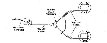
Parking brakes are completely mechanical and use only cables and levers to operate. When a parking brake lever is pulled (or when a parking brake pedal is pushed), these cables transmit the necessary force to keep the vehicle in place or to stop the vehicle. Most vehicles have drum brakes on their rear wheels; so, when the parking brake is pulled, the cables will pull a lever that compress the brake shoes to stop the vehicle.

In case of disc brakes in the rear, the hand brakes actuates a separate set of brake pads in the rear calipers. These pads are very small in size and are clamped mechanically only against the brake rotor.


Types of Parking Brakes
There are two types of vacuum servo brakes, both having a piston or a diaphragm operating in a cylinder. A small vacuum reservoir is there to provide vacuum for brake application even after the engine is switched off and a non-return valve provided between inlet manifold and vacuum reservoir.
The control unit consists of two valves.
Type1:
Both the sides of piston are exposed to atmosphere when brakes are in released position and on one side engine vacuum is applied during braking. The pressure difference between the two sides move the piston and activate the linkage.
Type 2:
Both the sides of piston are exposed to engine vacuum, when brakes are in released position and on one side is opened to atmosphere when the brakes are applied. The pressure difference between the two sides move the piston and activate the linkage.
The second type is called ‘suspended vacuum’ and it is commonly used due to more rapid action.
Working(Type 2):
When the brake pedal is free, upper valve in the control unit is closed and the lower one is open. Thus both sides of the piston in the servo cylinder are exposed to engine vacuum. If the brakes are applied, the pressure of the brake fluid pushes the piston in the control unit up, thereby closing the lower valve and opening the upper valve. Thus left side of servo piston is exposed to atmospheric pressure and move the piston to the right side. Thus gives the power assistance.
Hand brake:
The parking brake, also called hand brake, emergency brake, or e-brake, is used to keep the vehicle stationary and in many cases also perform an emergency stop, its main purpose is as a parking brake.. It is located either between the front two seats or to the left of the gas and brake pedal.
A car’s handbrake is the lever to a completely mechanical braking system, which will bypass the primary hydraulic system if it fails. When the handbrake is applied, the brake cable passes through an intermediate lever, to increase the force of the pull, this force is then split evenly between the brakes by an equaliser.A ratchet on the handbrake lever keeps the brake on once it is applied. A push button disengages the ratchet and frees the lever.
Parking brakes are completely mechanical and use only cables and levers to operate. When a parking brake lever is pulled (or when a parking brake pedal is pushed), these cables transmit the necessary force to keep the vehicle in place or to stop the vehicle. Most vehicles have drum brakes on their rear wheels; so, when the parking brake is pulled, the cables will pull a lever that compress the brake shoes to stop the vehicle.
Inside the brake drum, the secondary cable controlled by the hand lever is attached to a lever which is fulcrumed at one of the brake shoes. The lever also supports one end of the strut, whose other end is supported on the other shoe. When the hand-brake lever is pulled up, the cable pulls the lever, pressing the left shoe directly, while the right shoe takes up the reaction. Thus both shoes are moved outwards to apply brakes.
Types of Parking Brakes
There are four basic types of parking brakes:
Stick lever – found in older models and located under the instrument panel
Center lever – located between front bucket seats and seen in many newer model vehicles
Pedal – located on the floor to the left of the other pedals
Electric or push button – located on console with other controls
Stick lever – found in older models and located under the instrument panel
Center lever – located between front bucket seats and seen in many newer model vehicles
Pedal – located on the floor to the left of the other pedals
Electric or push button – located on console with other controls
- Cable-pull systems
- Electric-hydraulic caliper systems
- Full electric drive-by-wire systems
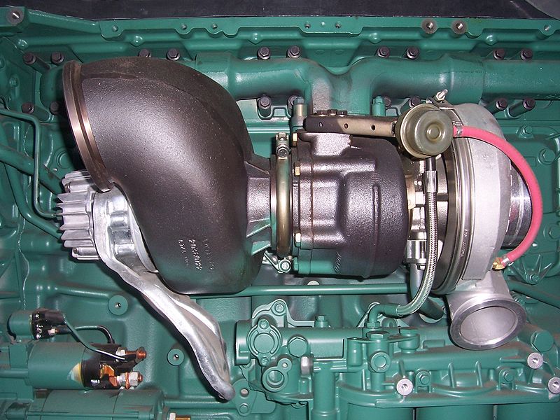
Engine Exhaust Brakes
An exhaust brake is a means of slowing a diesel engine by closing off the exhaust path from the engine, causing the exhaust gases to be compressed in the exhaust manifold, and in the cylinder. Since the exhaust is being compressed, and there is no fuel being applied, the engine works backwards, slowing down the vehicle. The amount of negative torque generated is usually directly proportional to the back pressure of the engine.
Exhaust brakes are generally installed directly behind the turbocharger turbine outlet, but can be installed virtually anywhere in the exhaust system. A simple exhaust brake consists of a butterfly valve inside of a tubular housing. A solenoid or mechanical attachment opens/closes the exhaust brake as necessary. In the open position, exhaust flows normally. In the closed or partially closed position, exhaust backpressure is greatly increased.
The backpressure works against the engine as it pumps air out of the cylinders, helping to slow down the engine and therefore the vehicle. Some exhaust brakes are completely mechanical, while others communicate directly with the engine's PCM (computer) to provide precision on-demand braking. Exhaust brakes are great for controlling speeds when towing downhill or bringing heavy loads to a halt while saving the truck and trailer brakes by reducing use.
Turbocharged Exhaust Brakes
When butterfly valve is closed, in the exhaust manifold there is no exhaust emissions so the turbine blades of the turbocharger cannot work, but because turbine blades has the blocking effect, and this effect can make lower inlet pressure of the diesel engine than it with no turbocharger, so air intake into the engine reduces which not only reduces the fuel consumption but also speed of the engine.
Hydro Elastic Suspension System
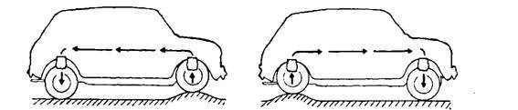
A system where the front and rear suspension systems were connected together in order to maintain the level of the car when driving. The front and rear suspension units have Hydrolastic displacers, one per side. These are interconnected by a small bore pipe. Each displacer incorporates a rubber spring. Damping of the system is achieved by rubber valves.
This suspension is intended to improve the vehicle’s resistance to pitch, the tendency of the body to oscillate in a fore-and-aft direction when the front springs are compressed and the rear springs are expanded simultaneously. The continuous forward and backward pitching motion provides a most uncomfortable ride, which may become serious when the frequency of vibration of front and rear springs is the same.

During this sequence the liquid has to pass the damper valve in each unit, and the restriction to liquid flow at the valves and in the pipelines damps out the tendency of pitch oscillation.


5.Torsional shear spring:
It consists of an inner metal shaft(solid or tube) an outer trough-like shell between
which rubber body is bonded and outer shell is fixed in the base plate.

Advantages of rubber springs:
Pneumatic Suspension


With fully supporting air suspension on both axles, different vehicle modes can be set,
• Normal driving position for city driving.
• Lowered driving position for high speeds to improve driving dynamics and air resistance.
• Raised driving position for travel off-road and on poor road surfaces.
Hydro Elastic Suspension System
A system where the front and rear suspension systems were connected together in order to maintain the level of the car when driving. The front and rear suspension units have Hydrolastic displacers, one per side. These are interconnected by a small bore pipe. Each displacer incorporates a rubber spring. Damping of the system is achieved by rubber valves.
This suspension is intended to improve the vehicle’s resistance to pitch, the tendency of the body to oscillate in a fore-and-aft direction when the front springs are compressed and the rear springs are expanded simultaneously. The continuous forward and backward pitching motion provides a most uncomfortable ride, which may become serious when the frequency of vibration of front and rear springs is the same.
The Hydrolastic suspension layout on a vehicle uses inter-connected rubber displacer units installed between the frame and the independent suspension linkage controlling the wheel. The interconnection is carried out using two pipes. One pipe links the left-hand side units together and the other on the right-hand side.
The system is pressurized with an anti-freeze liquid(consists of 49% alcohol, 49% distilled water 1% triethanolamine phosphate 1% sodium mercaptobenzothiazole) after removing air. Each displacer unit contains a rubber spring; metal separating member, which holds two rubber damper valves; rubber diaphragm attached to the suspension linkage, which holds the wheel; and a metal body, which is secured to the frame of the vehicle. Each displacer unit contains a rubber spring, and damping is achieved by the displaced fluid passing through rubber valves. The displaced fluid passes to the displacer of the paired wheel, thus providing a dynamic interaction between front and rear wheels.
Since road irregularities normally cause the vehicle to pitch, roll and bounce, the operation of the hydrolastic system under these conditions is discussed. A sudden upward movement of the front wheel causes the diaphragm to displace the liquid through the damper. This action is turn forces liquid along the pipe to the rear unit where it moves the diaphragm and raises the rear of the car to the level of the front. When the front wheel descends, the liquid returns and the vehicle comes to its normal riding position.
When a vehicle is cornering, the body of the vehicle tilts or rolls outwards due to centrifugal force. This tilting action is apparent when ‘soft’ conventional springs are used. The hydrolastic system is ‘soft’ during movement of a single wheel, but if the two outside suspension units are loaded during cornering, a stiffening of the hydrolastic system occurs. Under this type of loading displacement of the fluid from one unit to the other does not occur. Instead the increased liquid pressure deflects the rubber springs, which provide a marked resistance to the tilt of the body. During bouncing of the vehicle four wheels deflect at the same time. To resist this motion all the hydrolastic units perform in the similar way as to react to roll.
Rubber Suspension:
Rubber springs are used as bumping and rebound stops. When a suspension springs reaches its limit of travel, these prevents the metal-metal contact.
1.Compression spring
It is more reliable and simple construction.
It can resist a load in large magnitudes.
However it’s use is limited because a mechanical guide must be provided with this.
2.Compression-shear spring:
The load is carried partly by shear and partly by compression.
Large strains can be allowed in the body.
3.Steel-reinforced spring:
Steel helical spring bonded in the rubber body.
Can take up to 20% of the load
Has greater stroke/diameter ratio and used without any mechanical guide
4.Face shear spring:
It consists of a thick disc rubber having metal plates bounded on
It’s flat surfaces and axially precompressed.
It operates about the axis and takes shear load.

It consists of an inner metal shaft(solid or tube) an outer trough-like shell between
which rubber body is bonded and outer shell is fixed in the base plate.
It can take shear loads.

- It can store greater energy per unit weight than steel springs.
- It has good damping properties.
- No squeaking sound.
- More reliable.
- It doesn’t require lubricant.
Air suspension is a controllable form of vehicle suspension. With air suspension, it is simple to achieve self-levelling and
it is therefore generally integrated into the system.Air suspension is used in place of conventional steel springs in heavy vehicle applications such as buses and trucks, and in some passenger cars.
The purpose of air suspension is to provide a smooth, constant ride quality, but in some cases is used for sports suspension. Modern electronically controlled systems in automobiles and light trucks almost always feature self-leveling along with raising and lowering functions.
Construction
It Comprises of compressor for supplying air to air tank and air bag is a composite of rubber and polyurethane, which provides structural integrity, air-tight construction, toughness against light abrasion from road debris and sand, and resistance to salt and chemical corrosion.Pressure maintained – 5.6 to 7 kg/ sq.m or 240MPa. Air bags are placed on each wheel in the place of coil springs.

Air springs are basically installed on the rear and front axles. The
incoming air is first passed through the filter, where the dust is filtered and
then the air is passed into the compressor. The compressed air is generated by means of a single stage piston compressor with integrated air dryer. In order to avoid oil contamination of the U-bellows and the dryer cartridge, the compressor is a so-called dry running compressor.. Then this
pressure is sustained in the accumulator tank. This accumulator has a safety
relief valve(discharge valve), which acts as a safety device by opening when the air pressure
goes above 250 MPa. The air is then conveyed to elevate control valve and then
through leveling valves up to the air springs.
(interfaces) and its internal control parameters.
• Normal driving position for city driving.
• Lowered driving position for high speeds to improve driving dynamics and air resistance.
• Raised driving position for travel off-road and on poor road surfaces.
The basic advantages of self-levelling are:
• Static compression remains the same, irrespective
of vehicle loads (see overleaf). The space requirement in the wheel arches for
free wheel movement kept to a minimum, which has benefits for the overall use
of available space.
• The vehicle body can be suspended more softly,
which improves driving comfort.
• Full compression and rebound travel is maintained,
whatever the load.
• Ground clearance is maintained, whatever the
load.
• There are no track or camber changes when vehicle
is laden.
• Less wear to ball joints due to reduced working
angle.
• Greater loads are possible if required.
Drive by wire


Drive by wire
Drive by wire, DbW, by-wire, Steer-by-wire, or x-by-wire technology in the automotive industry is the use of electrical or electro-mechanical systems for performing vehicle functions that were traditionally achieved by mechanical linkages. This technology replaces the traditional mechanical control systems with electronic control systems using electromechanical actuators and human-machine interfaces such as pedal and steering feel emulators. Components such as the steering column, intermediate shafts, pumps, hoses, belts, coolers and vacuum servos and master cylinders are eliminated from the vehicle.
Drive By Wire Technology completely depends upon the electromechanical control system. Main component of this system is ECM(Engine Control Module). When we apply any action sensor sends signal to ECM and Actuator Actuates. This ECM is further connected to several system. ECM controls the signal and send signals to suitable system.
Drive by Wire technology is divided into the following sub-systems which operate these systems:
Throttle-by-Wire - Controls function of throttle
Brake-by-Wire- Controls braking system
Steer-by-Wire- Controls steering system
Shift-by-Wire- Controls transmission system
Park-by-Wire- Controls Parking Brake
1. Steer By Wire System
In Steer by wire system, there is no any mechanical linkages between the steering wheel and vehicle wheel. Angle of Steering rod is sensed by sensor and ECM receives the signal of Sensor. Environmental sensor in this system analyze the environmental factors like yaw or roll over position and sends the signal to ECM.
Advantages of Steer by Wire
- More space available in the engine compartment
- Due to absence of steering Column, Interior Styling is more versatile.
- Steering Response can be easily adjusted by monitoring driving characteristics.
Most of Automotive technology used today has replaced traditional throttle linkages by cables. In throttle by wire system, accelerator sensor senses the position of accelerator pedal. ECM actuates servo pump which actuates butterfly valve by electronically operated throttle and this position of throttle is continuously monitored by ECM and signal is sent to the ECM by using a feedback circuit.
Advantages of Throttle By Wire :
Maintains the stability of Vehicle.
Controls A/F Ratio i.e. Fuel Consumption.
Brake By Wire
Brake By Wire System replaces mechanical and hydraulic components with electronic sensor and actuators to control the braking system.
Advantages of Brake By Wire :
- Noiseless operation and elimination of vibration.
- Better Space Utilization due to lesser space required in making engine compartment.
- Allows ECM to integrate torque management with cruise Control, Stability Control & Traction Control.
- Reduces overall weight of System with improving air fuel efficiency.
No comments:
Post a Comment