Collision avoidance system:

The
Forward Collision Warning (FCW) system uses a radar to detect vehicles
or obstacles in front of the car. The system calculates the distance to
the object in front and, if the car gets close enough that there is a
risk of collision, sounds an alarm and displays a visual alert,
prompting the driver to apply the brakes. It’s important to note that FCW systems do not take full control of the vehicle or keep the driver from operating it.
It will significantly reduce the chance of a crash or a fatal accident. GPS sensors can detect fixed dangers such as approaching stop signs through a location database.
It will significantly reduce the chance of a crash or a fatal accident. GPS sensors can detect fixed dangers such as approaching stop signs through a location database.
Radar or Lidar Monitoring


The
radar unit sends out waves that bounce off of surfaces (cars, trucks,
bicycles, pedestrians, etc.) and return back to the vehicle’s
forward-mounted sensor.
As
fast as these radio waves are, they still take a little bit of time to
travel from one place to another, so the collision avoidance system can
use the time it takes for the waves to bounce back to calculate
distance—in this case, the distance from the car to whatever is in front
of it. This allows the system to give a visual (flashing lights) and
audible (beeping alarm) warning signal if the car is getting too close
to something ahead of car.

On some systems, radar pings are sent 20 times per second, allowing it to warn of split-second changes in traffic.
On Board Diagnostic (OBD)
OBD is a computer-based system originally designed to reduce emissions by monitoring the performance of major engine components. The OBD system is an on-board computer that communicates with other systems, including the ECU, TCU and more. A basic OBD system consists of an ECU (Electronic Control Unit), which uses input from various sensors (e.g., oxygen sensors) to control the actuators (e.g., fuel injectors) to get the desired performance. The “Check Engine” light, also known as the MIL (Malfunction Indicator Light), provides an early warning of malfunctions to the driver.
Early versions of OBD would simply illuminate a malfunction indicator light or "idiot light" if a problem was detected but would not provide any information as to the nature of the problem. Modern OBD implementations use a standardized digital communications port to provide real-time data in addition to a standardized series of diagnostic trouble codes, or DTCs, which allow one to rapidly identify and remedy malfunctions within the vehicle. A modern vehicle can support hundreds of parameters, which can be accessed via the DLC (Diagnostic Link Connector) using a device called a scan tool.
The OBD require that all components and subsystems which have an emission impact and which are connected to an Engine Control Unit (ECU) need to be monitored and diagnosed. The components can be divided into:
- Sensors: O2 sensor, temperature sensors, pressure sensors, etc.
- Actuators: Fuel injectors, ignition coils, throttle blades, cam phasers, EGR valve, etc.
On the system side, several subsystems have to be monitored such as a malfunction of a complete subsystem which leads to a certain emission increase. Such subsystems are:
- Fuel Injection System
- Ignition system
- Exhaust gas cleaning system
- Canister purge system


When the OBD system identifies an issue, it turns on a warning light in the dash (generally, the Check Engine Light), and then stores a trouble code (called a DTC, or diagnostic trouble code). A mechanic can connect a scan tool to the OBD connector under the dash and read this code.
All OBD-II cars have a connector located in the passenger compartment easily accessible from the driver's seat. The port, also known as the diagnostic connector is usually located behind the dashboard, above the brake pedal. A cable is plugged into the OBD-II connector and connected scan tool. The port allows the scan tool to gain information about the vehicle.
Advantages of OBD-II over OBD-I
OBD-II is an improvement over OBD-I in both capability and standardization. The OBD-II standard specifies the type of diagnostic connector and its pinout, the electrical signaling protocols available, and the messaging format. OBD-II is a sort of computer which monitors emissions, mileage, speed, and other useful data. The OBD-II standard provides extensible lists of DTCs.
OBD-II Diagnostic Trouble Codes are 4-digit, preceded by a letter:
P for engine and transmission (powertrain)
B for body
C for chassis
U for network.


P0520- Engine Oil Pressure Sensor/Switch Circuit Malfunction
C0000- Vehicle Speed Information Circuit Information Malfunction.
U0164- Lost Communication with HVAC Control Module.
B0540- Speedometer Circuit.
Reading OBD-II

OBD-III, which is still a concept, is advancement over OBD-II which will be equipped with telemetry. Using a radio transponder, OBD-III equipped vehicle will be able to send emissions problem directly to the regulating authority. It will report the Vehicle Identification Number (VIN) and the DTC. This can be done via cellular or satellite link as soon as the MIL turns on.
All OBD-II cars have a connector located in the passenger compartment easily accessible from the driver's seat. The port, also known as the diagnostic connector is usually located behind the dashboard, above the brake pedal. A cable is plugged into the OBD-II connector and connected scan tool. The port allows the scan tool to gain information about the vehicle.
Advantages of OBD-II over OBD-I
OBD-II is an improvement over OBD-I in both capability and standardization. The OBD-II standard specifies the type of diagnostic connector and its pinout, the electrical signaling protocols available, and the messaging format. OBD-II is a sort of computer which monitors emissions, mileage, speed, and other useful data. The OBD-II standard provides extensible lists of DTCs.
OBD-II Diagnostic Trouble Codes are 4-digit, preceded by a letter:
P for engine and transmission (powertrain)
B for body
C for chassis
U for network.
Diagnostic Trouble Code
Diagnostic Trouble Codes (DTC) are values that correspond to a particular type of fault in the vehicle. There are two types of codes,
Generic-The definition for the code is defined in the EOBD / OBD-II standard and will be the same for all manufacturers.
Manufacturer Specific-Where manufacturers feel that a code is not available within the generic list, they can add their own codes. The definitions for these are set by the manufacturer.
Some generic codes are
P0500- Vehicle Speed Sensor Malfunction.P0520- Engine Oil Pressure Sensor/Switch Circuit Malfunction
C0000- Vehicle Speed Information Circuit Information Malfunction.
U0164- Lost Communication with HVAC Control Module.
B0540- Speedometer Circuit.
Reading OBD-II
OBD-III, which is still a concept, is advancement over OBD-II which will be equipped with telemetry. Using a radio transponder, OBD-III equipped vehicle will be able to send emissions problem directly to the regulating authority. It will report the Vehicle Identification Number (VIN) and the DTC. This can be done via cellular or satellite link as soon as the MIL turns on.
Voice warning system
A voice warning system for automobiles includes a microprocessor connected with the battery of an automobile, a plurality of sensors arranged on different parts of the engine and connected with the microprocessor, and two voice integrated circuits for storing voice messages, whereby the microprocessor will give voice messages to notify the driver of the conditions of the car thereby ensuring the safety of the driver.A voice warning system for an automotive vehicle comprising:
1. A plurality of sensors for detecting various abnormal conditions in an automotive vehicle, for outputting voice warning information in response to said sensors when one of said sensors detects an abnormal condition.
2. A relay for reducing to an audible level lower than an initial audible level an audio signal level sent from other audio equipment provided within the same vehicle so as not to interfere with the voice warning information, said means for reducing the audio signal level being activated by a signal sent from any one of said sensors, whereby the driver can hear the voice warning information clearly even when the audio equipment is operating.
A voice warning system process the following information
- an engine speed sensor
- a door positive sensing interface
- a hand brake sensing interface
- an engine oil sensing interface
- an engine temperature sensor
- a gasoline sensing interface
- a brake oil level detector
- an engine oil mileage interface
- an automatic transmission fluid interface


if the vehicle door is not closed, or said door negative sensing interface is positive and said microprocessor will immediately trigger integrated circuit to send out a warning message “Please close the door". if the engine oil is insufficient, said engine oil sensing interface will be at LOW condition and when the engine speed is higher than 0 revolution, said microprocessor will immediately send out the warning “Insufficient engine oil” through said loudspeaker. when the engine is overheated due to excessive running or insufficient cooling water, said engine temperature sensor will pick up the overheat condition which will be transmitted to said high-low temperature selection, and if the temperature of the engine exceeds a normal value after high-low temperature comparison, a signal will be sent to said microprocessor which will trigger the integrated circuit to send out the warning “engine overheated”
Key-less Entry system
A remote keyless entry system consists of a remote, which, when activated within a certain range, can lock, unlock and perform various other functions within a car. Such a remote consists of a short-range radio transmitter that sends radio waves to a receiver unit inside the car, which triggers the aforementioned functions.
The tiny ‘car remote’ for any car consists of a short-range radio transmitter. When the remote is within a specific range (typically, 5-20 meters) from car, press one of its buttons, a coded signal, embedded in radio waves, is sent to a receiver unit installed inside the car. The receiver unit then decodes and translates that signal, which consequently locks/unlocks the doors, trunk of the car.


Unlike regular Remote key entry, PKE devices don’t typically require to push any buttons to lock/unlock the car. This is because, in addition to a radio transmitter, it also contains a receiver. The transponder (a combination of the words ‘transmitter’ and ‘responder’) inside the smart key doesn’t need a battery to work.


It allows the user to keep the key fob in their pocket while approaching the car, as the transponder inside the fob communicates with the receiver system of the car to open the doors and even activate the ignition from a distance. Furthermore, it does the latter without requiring the user to put the key in the ignition. To lock the car, the user can press a button on one of the door handles, touch a capacitive area on a door handle, or simply walk away from the car.
cars with KES: Mercedes Benz V-Class, BMW X4, Rolls Royce Cullinan, Mercedes Benz C Class, Hyundai Santro, Honda CR-V.


Engine Immobiliser
An Immobiliser or the Engine Immobiliser is an electronic security device which the modern cars use. The Engine Immobiliser uses an electronic chip embedded into the key fob.
An immobiliser is an electronic anti-theft security device which prevents engine start by an unauthorised person unless the correct key or fob is placed in the ignition barrel. If the correct key is used, transponder inside the key sends a signal to the reader(transponder in the key coil) which transfer signal to the receiver (ECU). If the signal is recognized by the ECU, the system allows user to start engine. If not the immobiliser disables few car systems that is necessary to start the engine. The ECU does NOT activate the fuel system and the ignition circuit if the code in the key & that stored in the immobilizer does not match.

 The
immobiliser is strongly connected to the car security system, so any
unauthorised access to the car that is detected by the security system
(movement detectors, infra-red sensor, sonic sensor and many others,
depending on the security system) automatically trigger the immobiliser
and any other alarm aims such a horn and flashing headlights.
The
immobiliser is strongly connected to the car security system, so any
unauthorised access to the car that is detected by the security system
(movement detectors, infra-red sensor, sonic sensor and many others,
depending on the security system) automatically trigger the immobiliser
and any other alarm aims such a horn and flashing headlights.
Car alarm can be activated by infra-red signal generated by the fob or a key ring and received by optical sensing unit placed in the car.
Another type is a radio control system. Radio wave is created by the fob or the key and received by car antenna. In both examples the signal is unique for each car and only this one signal is recognised by the ECU.
Anti Theft Alarm:
An 'Anti-theft alarm system' or Car Alarm is a type of device or method which alerts when there is an unauthorized access to a motorcycle or car.
The Anti-theft alarm system works with the help of sensors installed in and around the vehicle. An impact or the movements inside the car activates the sensors. This, in turn, triggers the Anti-theft alarm system and sounds the alarm. The alarm goes off and alerts the owner/people. Even, the change in vehicle’s position can alert the tilt sensor and activates the anti-theft alarm system.

Alarm system uses few different types of sensors to protect the car:
Ultrasonic: car interior is covered by an ultrasonic signal; any change in the strength on the signal pattern activates the alarm
Voltage drop or current drain: any drop of voltage (disconnecting the battery) or current drain (by switching on interior light)
Infra-red: detecting any disruption of the beam transmitted between two points inside of the car.
Direct earth contact: detected by the bonnet, boot and door switches when an earth contact happens.
Pressure Sensor:This type of sensor system checks and monitors the changes experienced in air pressure created when a window is broken or cars doors are forcibly opened. When a suspicious pressure change is detected, the alarm is triggered. Some pressure sensors employ the in-built speakers of the car, while many others have their own speakers.
Window Sensor:Without the doors of a car being meddled with, a car can still be stolen by just breaking the windows. This is a trick used by thieves many a time. To prevent such a theft, window sensor alarms are used. The basic window sensor alarm can detect glass or window breakage, using a microphone to pick up the sound of breaking glass.
Breaking glass has its own distinctive sound frequency (pattern of air-pressure fluctuations). The microphone converts this to an electrical current of that particular frequency, which it sends to the brain.
Door Sensor:The door sensor alarm is probably the simplest of all car alarms. When the front trunk or doors of the car open, the system gets activated and the alarms start ringing. Most car alarm systems utilize the switching mechanism that is already built into the doors. In modern cars, opening a door or trunk turns on the inside lights.
Blind spot detection
The system is also called blind spot monitoring and blind spot information system. Blind spots are the areas outside of a vehicle that the driver is unable to see. Blind spots can be caused by the window pillars, headrests, passengers, and other objects.
While driving every part of the car that isn't glass creates a blind spot. That means vehicles with larger window pillars have larger blind spots, vehicles with smaller rear view windows have larger blind spots, and both cargo and passengers can also create additional blind spots.
 Blind
spots are relatively small close to a vehicle, but they cover larger
areas further away. At even moderate distances, a blind spot caused by
an A-pillar can obscure large objects such as cars and people. Another
type of vehicular blind spot exists in the space between the driver’s
peripheral vision and the area reflected by the rear-view mirrors. This
type of blind spot can swallow up entire vehicles, which is why it's so
dangerous to change lanes without looking to the left or right.
Blind
spots are relatively small close to a vehicle, but they cover larger
areas further away. At even moderate distances, a blind spot caused by
an A-pillar can obscure large objects such as cars and people. Another
type of vehicular blind spot exists in the space between the driver’s
peripheral vision and the area reflected by the rear-view mirrors. This
type of blind spot can swallow up entire vehicles, which is why it's so
dangerous to change lanes without looking to the left or right.
Blind spot detection is a key technology among driver aids that provide 360 degrees of electronic coverage around the car. This circle of safety also includes adaptive cruise control, lane departure warning, rear and front parking sonar, the rear traffic alert, and parking cameras (ranging from rear-only through four cameras providing a birds-eye view of the car.


 In
other types, use radar (electromagnetic waves that bounce off solid
objects and return an echo indicating if they're there) and are mounted
in the rear of the car, in the vicinity of the back bumpers. These
sensors are valued for both their fast response time and their wide
effective range which emits a 360-degree wave.
In
other types, use radar (electromagnetic waves that bounce off solid
objects and return an echo indicating if they're there) and are mounted
in the rear of the car, in the vicinity of the back bumpers. These
sensors are valued for both their fast response time and their wide
effective range which emits a 360-degree wave.
The Blind Spot Intervention (BSI) System of Infinity will start gently applying the brakes on the side of the car away from the danger, causing the vehicle to slowly swerve back toward the safe lane. Audi's BLIS, will detect cars.
Rear view cameras


Tire pressure monitoring systems or Deflation Detection Systems:


cars with TPMS : Maruti Suzuki Baleno Mercedes-Benz V-Class, Maruti Suzuki Wagon R, Tata Harrier, Nissan Kicks, BMW X4
Automotive Navigation Systems:
Automotive
navigation system is used in in-vehicle infotainment systems.
Automotive navigation system uses satellite navigation technique.
Navigation systems use top view for the map. These systems use global
positioning system (GPS) to facilitate intelligent navigation.
GLOBAL POSITIONING SYSTEM (GPS):
GPS is used to find the systems current position. It helps in determining the co-ordinates (longitude and latitude) of the system’s position. These co-ordinates are mapped to the unit maps database which helps in determination of the system’s location.


2. Control Segment: The control segment of GPS consists of five tracking stations distributed around the earth of which one, located in Colorado Springs, is a Master Control Station. The control segment tracks all satellites, ensures they are operating properly and computes their position in space. The computed positions of the satellites are used to predict where the satellite will be later in time. These parameters are uploaded from the control segment to the satellites and referred to as broadcast ephemeredes.
3. User Segment: The GPS user segment consists of the GPS receivers and the user community. Almost all GPS tracking equipment have the same basic components: an antenna, an RF (Radio Frequency) sections a microprocessor, a control and display unit (CDU), recording device and a power supply. Usually all component, with the exception of the antenna, are grouped together and referred to as a receiver. GPS receivers convert SV signals into position, velocity, and time estimates. Four satellites are required to compute the four dimensions of X, Y, Z (position) and time. GPS receivers are used for navigation, positioning, time dissemination, and other research.
4. GPS Signals: Each GPS satellite continuously broadcasts ranging signals containing wealth of information. The information contained in GPS signals includes the carrier frequencies (L1 & L2), codes (coarse acquisition [C/A] & Precise [P]) and the navigational message. These allow users to measure their pseudo ranges and to estimate their positions in passive, listen only mode.
Basic principle of GPS
The basic principle of determining the position by using GPS satellites is based on measurement of distances from the point of observations to the satellite. This is done by comparing the reading of transmitter antenna time with the receiver antenna time. It cannot be assumed that the two clocks will be strictly in synchronization since the clocks used in the present type of receivers are quartz clocks to reduce the cost of the receiver. The observed signal time will have a systematic synchronization error. Since the measured range has got this systematic error in it, the computed distances will also be biased, and therefore, these are called pseudo-range. To compute the position based on this pseudo-range, the error due to time bias has to be corrected and therefore, this is also taken as an unknown and determined before deriving the true range. As we know from the simple formulate of distance computation that
 Satellite
Navigation is based on a global network of satellites that transmit
radio signals in medium earth orbit. The basic GPS service provides
users with approximately 7.8 meter accuracy, 95% of the time, anywhere
on or near the surface of the earth. To accomplish this, each of the 32
satellites emits signals to receivers that determine their location by
computing the difference between the time that a signal is sent and the
time it is received. GPS satellites carry atomic clocks that provide
extremely accurate time. The time information is placed in the codes
broadcast by the satellite so that a receiver can continuously determine
the time the signal was broadcast. The signal contains data that a
receiver uses to compute the locations of the satellites and to make
other adjustments needed for accurate positioning. The receiver uses the
time difference between the time of signal reception and the broadcast
time to compute the distance, or range from the receiver to the
satellite.
Satellite
Navigation is based on a global network of satellites that transmit
radio signals in medium earth orbit. The basic GPS service provides
users with approximately 7.8 meter accuracy, 95% of the time, anywhere
on or near the surface of the earth. To accomplish this, each of the 32
satellites emits signals to receivers that determine their location by
computing the difference between the time that a signal is sent and the
time it is received. GPS satellites carry atomic clocks that provide
extremely accurate time. The time information is placed in the codes
broadcast by the satellite so that a receiver can continuously determine
the time the signal was broadcast. The signal contains data that a
receiver uses to compute the locations of the satellites and to make
other adjustments needed for accurate positioning. The receiver uses the
time difference between the time of signal reception and the broadcast
time to compute the distance, or range from the receiver to the
satellite.
With information about the ranges to three satellites and the location of the satellite when the signal was sent, the receiver can compute its own three-dimensional position. An atomic clock synchronized to GPS is required in order to compute ranges from these three signals. However, by taking a measurement from a fourth satellite, the receiver avoids the need for an atomic clock. Thus, the receiver uses four satellites to compute latitude, longitude, altitude, and time.

 for your knowledge
speed of satellite -3.9km/s
satellite altitude from ground-20000km-35000km
satellite completes an orbit in 11hrs 58mins
clock delay of 1ns-error of 30cm or 1 foot
Infotainment systems
 Head Unit (HU)
is regarded as the master of the infotainment network. It contains one
or more CPUs for real-time communication purposes ( gateway CPU) with
other peripheral components like memory, CAN transceivers, Media
Oriented System Transport (MOST) transceiver, and other components.The gateway CPU is connected to the main CPU with an internal bus. One CPU(Main CPU) for the user interface with infotainment application. The
main CPU is not connected to the MOST command/control channel and the
CAN network, so all the messages from the main CPU to end user are sent
and received over the gateway CPU.
Head Unit (HU)
is regarded as the master of the infotainment network. It contains one
or more CPUs for real-time communication purposes ( gateway CPU) with
other peripheral components like memory, CAN transceivers, Media
Oriented System Transport (MOST) transceiver, and other components.The gateway CPU is connected to the main CPU with an internal bus. One CPU(Main CPU) for the user interface with infotainment application. The
main CPU is not connected to the MOST command/control channel and the
CAN network, so all the messages from the main CPU to end user are sent
and received over the gateway CPU.
IVI System Framework


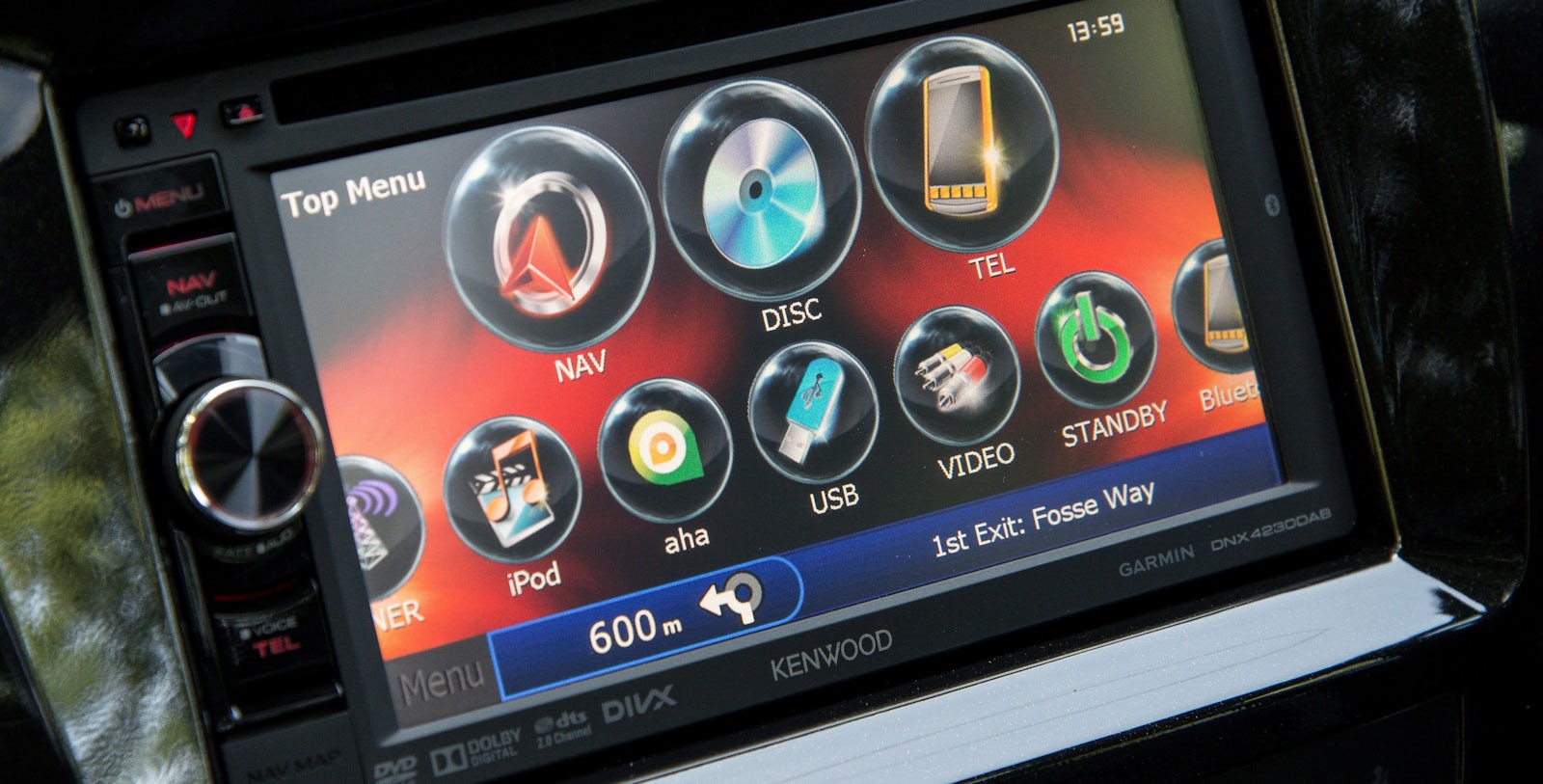
In-vehicle infotainment system comprises of the following services:
I) Entertainment Services:
Audio: The audio runs through radio, CD player, or by playing tracks with USB or phone connectivity; it may support MP3 or WMA format based on the OS (Operating system).The basic components of the audio systems are speakers, sub woofers, and amplifiers.
Video: The car should be equipped with an exclusive multimedia system. Today, cars have internet TV and also have an option to access mobile TV. However, there are several challenges such as a power source and signal reception during motion that affect the quality of the pictures or videos.
II) Phone Services:
Enhancing communication Services: The IVI system provides calls and messaging services with a hands-free experience to attend calls while driving. The driver can use Bluetooth headsets to communicate and can also use voice commands to operate the system.
cars with KES: Mercedes Benz V-Class, BMW X4, Rolls Royce Cullinan, Mercedes Benz C Class, Hyundai Santro, Honda CR-V.
Central locking system
Central locking system (also known as electric door locks or power locks) allows the driver or front passenger to simultaneously lock or unlock all the doors of an automobile or truck, by pressing a button or flipping a switch.
Today, many cars with power door locks also have a radio frequency remote keyless system, which allows a person to press a button on a remote control key fob. It allows the windows to be opened or closed by pressing and holding a button on the remote control key fob, or by inserting the ignition key and holding it in the lock or unlock position in the external driver's door lock. The remote locking system confirms successful locking and unlocking through either a light or a horn signal.
Door assembly consists of catch, pawl and latch. The door lock striker is attached to the body pillar. Under closing operation the door lock striker gets caught by the latch and hold in the closed position and centres the door. The pawl positively locks the catch in position. This lock condition is automatically aborted when opening procedures begin. For this process the forces acting on inner or outer door handle are transferred to the pawl and cause the catch release to open the door. The door lock striker stays in the position while the catch swivels go into an open position.
In a case of operation methods central locking system consists of two types of actuators: electromagnetic and pneumatic.
Electromagnetic actuators rely on solenoids which lock or unlock doors using current going in both directions (open/closed) through an electric module. On this kind of system two types of arrangements are in use. First one uses separate relays for each of action taken by the system. One dedicated to open and another one to close the door. Both of them are controlled by a transistor switching the circuit operated by the capacitor (storage for energy necessary to operate system) which is releasing current necessary to activate the locks. Another type uses two capacitors and two relays working as a tandem. One pair is responsible for locking and another for unlocking. When the circuit is closed a current is discharged from the capacitor and the lock is either opened or closed.
Pneumatic actuators are driven by a pneumatic central unit which controls vacuum/pressure pump. When vacuum is applied actuators acting on mechanism lock or unlock the door. The vacuum pump is driven by electric motor which is working in both directions. Forward rotation creates a compressor action (doors open), while backwards rotation creates vacuum (doors close). Polarity on the electric motor is changed by a change-over control switch.
In most modern cars electrical locking system replaced mechanical unit due to a demand for quality and reliability.
A small electric motor turns a series of spur gears that serve as a gear reduction. The last gear drives a rack-and-pinion gearset that is connected to the actuator rod. The rack converts the rotational motion of the motor into the linear motion needed to move the lock.
This actuator can move the metal hook shown in this photo to the left or right. When mounted in the car, it is vertical, so the hook can move up or down. It mimics the motions when the knob is pulled up or pushed down.
 | ||
| worm and nut type |

while the motor can turn the gears and move the latch, if the latch is moved it will not turn the motor. This is accomplished by a neat centrifugal clutch that is connected to the gear and engaged by the motor.
When the motor spins the gear, the clutch swings out and locks the small metal gear to the larger plastic gear, allowing the motor to drive the door latch. If the the door latch is moved manually, all of the gears will turn except for the plastic gear with the clutch on it.
The main advantages of electrical locking system are:
- symmetrical design,
- smaller and lighter in comparison to a mechanical unit
- only one lock version per vehicle
- door handles no longer move
- other supplementary functions, like an interior light or status indicator, can be easily introduced in electrical locking system because the lock is equipped with electronics, which can carry out these functions. Communications with the locks, power supply and security system take place via data can bus system.
An Immobiliser or the Engine Immobiliser is an electronic security device which the modern cars use. The Engine Immobiliser uses an electronic chip embedded into the key fob.
An immobiliser is an electronic anti-theft security device which prevents engine start by an unauthorised person unless the correct key or fob is placed in the ignition barrel. If the correct key is used, transponder inside the key sends a signal to the reader(transponder in the key coil) which transfer signal to the receiver (ECU). If the signal is recognized by the ECU, the system allows user to start engine. If not the immobiliser disables few car systems that is necessary to start the engine. The ECU does NOT activate the fuel system and the ignition circuit if the code in the key & that stored in the immobilizer does not match.
Car alarm can be activated by infra-red signal generated by the fob or a key ring and received by optical sensing unit placed in the car.
Another type is a radio control system. Radio wave is created by the fob or the key and received by car antenna. In both examples the signal is unique for each car and only this one signal is recognised by the ECU.
Anti Theft Alarm:
An 'Anti-theft alarm system' or Car Alarm is a type of device or method which alerts when there is an unauthorized access to a motorcycle or car.
The Anti-theft alarm system works with the help of sensors installed in and around the vehicle. An impact or the movements inside the car activates the sensors. This, in turn, triggers the Anti-theft alarm system and sounds the alarm. The alarm goes off and alerts the owner/people. Even, the change in vehicle’s position can alert the tilt sensor and activates the anti-theft alarm system.
Ultrasonic: car interior is covered by an ultrasonic signal; any change in the strength on the signal pattern activates the alarm
Voltage drop or current drain: any drop of voltage (disconnecting the battery) or current drain (by switching on interior light)
Infra-red: detecting any disruption of the beam transmitted between two points inside of the car.
Direct earth contact: detected by the bonnet, boot and door switches when an earth contact happens.
Car-alarm Transmitters:Most
car alarm systems comes with a portable keychain transmitter. With this
device, we can send instructions to the brain to control the alarm
system remotely.
Shock Sensor: Shock sensor alarms run on the concept of motion strength. Signals to the brain of the system by the sensors determine the strength of the motion and can detect whether someone is trying to push or hit or move the car. The brain of the system immediately gets the horn honking or activates the audio system to start playing loudly in order to alert.
Motion and Tilt Sensor:This
is another type of sensor alarm system which is used to alert from
towing away the car between places. Perimeter Scanners are installed in
these sensor systems, which are used in order to watch the car's
surroundings.The most common perimeter scanner is a basic radar system,
consisting of a radio transmitter and receiver. The transmitter sends
out radio signals and the receiver monitors the signal reflections that
come back. Based on this information, the radar device can determine the
proximity of any surrounding object.Shock Sensor: Shock sensor alarms run on the concept of motion strength. Signals to the brain of the system by the sensors determine the strength of the motion and can detect whether someone is trying to push or hit or move the car. The brain of the system immediately gets the horn honking or activates the audio system to start playing loudly in order to alert.
Pressure Sensor:This type of sensor system checks and monitors the changes experienced in air pressure created when a window is broken or cars doors are forcibly opened. When a suspicious pressure change is detected, the alarm is triggered. Some pressure sensors employ the in-built speakers of the car, while many others have their own speakers.
Window Sensor:Without the doors of a car being meddled with, a car can still be stolen by just breaking the windows. This is a trick used by thieves many a time. To prevent such a theft, window sensor alarms are used. The basic window sensor alarm can detect glass or window breakage, using a microphone to pick up the sound of breaking glass.
Breaking glass has its own distinctive sound frequency (pattern of air-pressure fluctuations). The microphone converts this to an electrical current of that particular frequency, which it sends to the brain.
Door Sensor:The door sensor alarm is probably the simplest of all car alarms. When the front trunk or doors of the car open, the system gets activated and the alarms start ringing. Most car alarm systems utilize the switching mechanism that is already built into the doors. In modern cars, opening a door or trunk turns on the inside lights.
Blind spot detection
The system is also called blind spot monitoring and blind spot information system. Blind spots are the areas outside of a vehicle that the driver is unable to see. Blind spots can be caused by the window pillars, headrests, passengers, and other objects.
While driving every part of the car that isn't glass creates a blind spot. That means vehicles with larger window pillars have larger blind spots, vehicles with smaller rear view windows have larger blind spots, and both cargo and passengers can also create additional blind spots.
Blind spot detection is a key technology among driver aids that provide 360 degrees of electronic coverage around the car. This circle of safety also includes adaptive cruise control, lane departure warning, rear and front parking sonar, the rear traffic alert, and parking cameras (ranging from rear-only through four cameras providing a birds-eye view of the car.
All
active systems, whether they use lasers, radars, or cameras, constantly
monitor the spaces around the vehicle. If they detect a vehicle in the
car’s blind spot, they pass a message to the driver, usually in the form
of an indicator light on either the dashboard or the side view mirrors
or on the inside of the front roof pillar nearest the mirror, or on an adjacent window frame.
Some systems also give the driver an audio warning if the turn signal
is activated when the blind spot monitor has been triggered. The most
sophisticated systems have some ability to intervene and prevent the
driver from merging into another lane when another vehicle is detected
in the blind spot.
The first such system was developed by Volvo Cars and
deployed in 2003. It used cameras placed in the car's side rear view
mirrors, and a computer processed the image from those cameras to see if
anything looked like a car and seemed to be approaching dangerously
into the area where the car might hit it while changing lanes.

The Blind Spot Intervention (BSI) System of Infinity will start gently applying the brakes on the side of the car away from the danger, causing the vehicle to slowly swerve back toward the safe lane. Audi's BLIS, will detect cars.
Rear view cameras
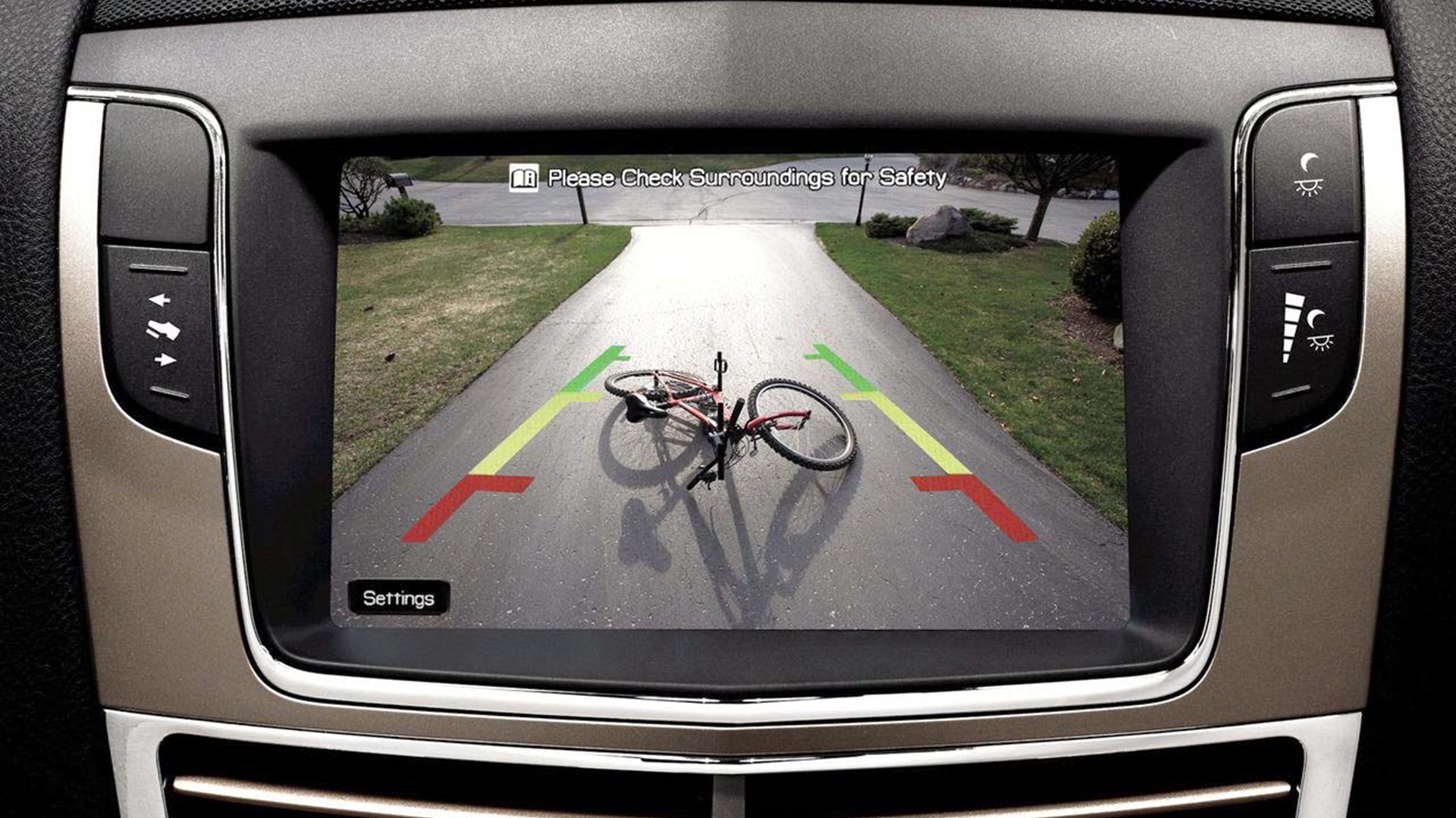
Rear
view cameras, often part of parking assistance systems, parking
guidance systems, backup camera and reversing camera is an indirect type
of blind spot monitoring system. Rear-view camera systems are generally
mounted to the lower outside areas of the vehicle or to the vehicle's
bumper. In wireless systems, images are transformed to radio signals,
transmitted and then converted from a radio signal back to a video image
once it reaches the receiver and monitor. Typically, these systems send
a video feed of the rear of the vehicle to a display in the center
console of the vehicle, giving the driver a sharp, unobstructed view of
the rear of their vehicle and all of the potential obstacles and
vehicles behind them with interactive track lines.
As far back as the late 1970s, large construction vehicles such as dump trucks and heavy mining equipment including dozers and scrapers began placing cameras on the back of the equipment to help operators with rear vision. Because the tractors and dump trucks used on strip mines are so large, and the mines themselves are so vast of a work area, rear visibility is limited, so operators couldn't see behind them when they needed to back up. This was especially true for the dump trucks and large bulldozers, as they frequently needed to reverse direction during a typical work day. To combat the lack of rear visibility, mechanics installed tiny cameras and connected them to a small monitor. Since some of the vehicles used on strip mines had no rear visibility, the makeshift cameras proved a valuable safety measure.
Infiniti's latest gadget, the 360-degree Around View Monitor camera system projects a bird's-eye view of the exterior of the vehicle on a liquid crystal display (LCD) monitor nestled in the center console below the dashboard. The system relies on four small cameras to create a complete picture that drivers can use during parking, backing up or driving in traffic. The cameras record raw digital footage, and software electronically straightens the images through electronic interpolation or pixel enhancement and the result is a real-time overhead (or bird's-eye) view of the vehicle.The camera system is also helpful when the driver needs to see oncoming traffic, as in the case of the blind alley.
 |
| around view monitor |
Wireless Backup Camera
This is an advanced type of reversing camera that does not require the use of cables between the camera itself and the display. It functions remotely. Wireless rear-view cameras usually have separate sources of power from the display. The cameras are usually powered by the same power source as the brake and thus switches on automatically when one engages the reverse gear. Majority of these backup cameras usually comes with a transmitter (near the camera) and a receiver (near the display) for relaying the signals and live images.
This is an advanced type of reversing camera that does not require the use of cables between the camera itself and the display. It functions remotely. Wireless rear-view cameras usually have separate sources of power from the display. The cameras are usually powered by the same power source as the brake and thus switches on automatically when one engages the reverse gear. Majority of these backup cameras usually comes with a transmitter (near the camera) and a receiver (near the display) for relaying the signals and live images.
Cars with blind spot detection: Chevrolet Cruze, Mercedes-Benz E-Class, Ford Focus, Honda Jazz, Volvo S60..etc
Tire pressure monitoring systems or Deflation Detection Systems:
A
tire pressure monitoring system (TPMS) is an electronic system designed
to monitor the air pressure inside the pneumatic tires on various types
of vehicles. TPMS report real-time tire-pressure information to the
driver of the vehicle, either via a gauge, a pictogram display, or a
simple low-pressure warning light.
TPMS can be divided into two different types.
1. Direct (DTPMS)
2. Indirect (ITPMS).
2. Indirect (ITPMS).
1.Direct tire pressure monitoring systems
uses individual sensors inside each tire.The sensors read internal
pressure, and sometimes temperature. The information received at the
module is analyzed, and any issues with any of the tires are sent to the
car's vehicle information system, or low-pressure light. Information is most often sent wirelessly as a radio signal. While some
systems are mounted outside the tire. Each sensor has a battery with a life of
about a decade. On most, the battery is not serviceable, and the entire sensor
must be changed.
A direct TPMS sensor consists of the following components
- pressure sensor
- analog-digital converter
- micro controller
- system controller
- oscillator
- radio frequency transmitter
- low frequency receiver, and
- voltage regulator (battery management).
2.Indirect tire pressure monitoring systems don't rely
on sensors to do the work, or at least not pressure sensors. The systems rely
on wheel speed sensor data to interpret the size of a tire based on how fast it
rotates, a small tire would rotate faster than a larger tire, and an
underinflated tire is smaller than one with proper inflation. All of this data
can be gleaned by electronic monitors within in the car, and then interpreted
using advanced programming and processing.

cars with TPMS : Maruti Suzuki Baleno Mercedes-Benz V-Class, Maruti Suzuki Wagon R, Tata Harrier, Nissan Kicks, BMW X4
Automotive Navigation Systems:
GLOBAL POSITIONING SYSTEM (GPS):
GPS is used to find the systems current position. It helps in determining the co-ordinates (longitude and latitude) of the system’s position. These co-ordinates are mapped to the unit maps database which helps in determination of the system’s location.
1. Space Segment: The space segment of GPS consists of 24 satellites fielded in nearly circular orbits with a radius of 26,560 km, period of nearly 12 hours and stationary ground tracks. The satellites are arranged in six orbital planes inclined at 55° relative to the equatorial plane, with four satellites distributed in each orbit. With this constellation, almost all users with a clear view of the sky have a minimum of four satellites in view. Each satellite receives and stores information from the control segment; maintain very accurate time through on board precise atomic clocks.
2. Control Segment: The control segment of GPS consists of five tracking stations distributed around the earth of which one, located in Colorado Springs, is a Master Control Station. The control segment tracks all satellites, ensures they are operating properly and computes their position in space. The computed positions of the satellites are used to predict where the satellite will be later in time. These parameters are uploaded from the control segment to the satellites and referred to as broadcast ephemeredes.
3. User Segment: The GPS user segment consists of the GPS receivers and the user community. Almost all GPS tracking equipment have the same basic components: an antenna, an RF (Radio Frequency) sections a microprocessor, a control and display unit (CDU), recording device and a power supply. Usually all component, with the exception of the antenna, are grouped together and referred to as a receiver. GPS receivers convert SV signals into position, velocity, and time estimates. Four satellites are required to compute the four dimensions of X, Y, Z (position) and time. GPS receivers are used for navigation, positioning, time dissemination, and other research.
4. GPS Signals: Each GPS satellite continuously broadcasts ranging signals containing wealth of information. The information contained in GPS signals includes the carrier frequencies (L1 & L2), codes (coarse acquisition [C/A] & Precise [P]) and the navigational message. These allow users to measure their pseudo ranges and to estimate their positions in passive, listen only mode.
The basic principle of determining the position by using GPS satellites is based on measurement of distances from the point of observations to the satellite. This is done by comparing the reading of transmitter antenna time with the receiver antenna time. It cannot be assumed that the two clocks will be strictly in synchronization since the clocks used in the present type of receivers are quartz clocks to reduce the cost of the receiver. The observed signal time will have a systematic synchronization error. Since the measured range has got this systematic error in it, the computed distances will also be biased, and therefore, these are called pseudo-range. To compute the position based on this pseudo-range, the error due to time bias has to be corrected and therefore, this is also taken as an unknown and determined before deriving the true range. As we know from the simple formulate of distance computation that
R = (X –
Xi)
2
+ (Y –Yi)
2
+ (Z –Zi 2)
Where X, Y & Z are the co-ordinate of the station, therefore unknown and Xi, Yi & Zi are the co-ordinates of the satellite, which is broadcast information.
To find the true range the time bias t is also has to be considering, therefore
To find the true range the time bias t is also has to be considering, therefore
R =
((X – Xi) 2
+ (Y –Yi) 2
+ (Z –Zi)) 2
+ TC
Where C is the velocity of light, R is pseudo-range and T is travel time. Now in this equation, there are four unknown therefore, to solve this at least 4 satellites will have to be observed. The minimum requirement in this case is
- To know the co-ordinates of satellite antenna
- To know the satellite time at the time of emission of the signal
- Minimum 4 satellites, 4th one required to determine the time bias.
With information about the ranges to three satellites and the location of the satellite when the signal was sent, the receiver can compute its own three-dimensional position. An atomic clock synchronized to GPS is required in order to compute ranges from these three signals. However, by taking a measurement from a fourth satellite, the receiver avoids the need for an atomic clock. Thus, the receiver uses four satellites to compute latitude, longitude, altitude, and time.
Car navigation systems receive signals from the gps satelites and identify the relative car position and direction by combining the information received fron the onboard sensors. The gps satelites can also help to find the route to the destination using various databases like road network database,traffic data database, Site information data and even the background data consisting of rivers bridges etc.
In-car GPS consists of three major components:
1. A GPS receiver. GPS is a receive-only system. We cannot transmit data or messages via GPS. A GPS receiver performs one and only one very simple function: It listens to GPS satellite signals and calculates its position relative to the surface of the earth, in the form of latitude and longitude.
2. A Detailed Map. The navigation system will come loaded with a detailed map of that country i.e. a database of every road and landmark in the entire country, and associated lat-long coordinates with the car. Sometimes, in smaller countries, it will also contain a map of neighboring countries.
3. An Inertial Navigation System. Using the gyroscopes and accelerometers or speed sensor can measure the motion of any body - including the car or airplane or submarine. When GPS is turned on, the navigation system in the car, it does not know the location of the car. The initial position fix is provided by the GPS receiver, and for most part this is really all that GPS contributes. Once position is fixed, it is matched against the map to figure out where the car is. As soon as we started driving, the inertial navigation system takes over: It knows how many millimeters or kilometers the car has moved, in which direction, where did the car turn, etc. etc. and thus it knows at any given moment exactly where the car is located and where it is headed.
Combining the use of signals from the satellites with interactive on-board maps, these systems can plot routes of travel to a given destination based on a number of variables. Some of these systems are interconnected with sources of traffic information, enabling them to automatically account for congestion en route while determining the best options to reach a destination.
speed of satellite -3.9km/s
satellite altitude from ground-20000km-35000km
satellite completes an orbit in 11hrs 58mins
clock delay of 1ns-error of 30cm or 1 foot
The
infotainment system can be described as a distributed, heterogeneous
hardware/software system, which provides entertainment functionalities
and information services to the drivers and passengers in the vehicle
through the interaction of several connected devices.

It mainly
comprises of a head unit along with a combination of components such as a
control panel, telematics device, and head-up display. The hardware
components are interconnected with certain standardized communication
protocols such as CAN network (CAN network or controller area network is
a robust vehicle bus standard and is designed to allow microcontrollers
and devices to communicate with each other in applications) and some wireless communication channels like Bluetooth.
I) Entertainment Services:
Audio: The audio runs through radio, CD player, or by playing tracks with USB or phone connectivity; it may support MP3 or WMA format based on the OS (Operating system).The basic components of the audio systems are speakers, sub woofers, and amplifiers.
Video: The car should be equipped with an exclusive multimedia system. Today, cars have internet TV and also have an option to access mobile TV. However, there are several challenges such as a power source and signal reception during motion that affect the quality of the pictures or videos.
II) Phone Services:
Enhancing communication Services: The IVI system provides calls and messaging services with a hands-free experience to attend calls while driving. The driver can use Bluetooth headsets to communicate and can also use voice commands to operate the system.
cars with voice recognition infotainment system: Ford Rangers, BMW X5, Honda Civic.
III) Information Services:
This service offers many useful features to protect the car and get information for vehicle safety and ease of driving.
Rear parking assistance: The system can help drivers in getting a better idea about the objects or vehicles at the rear side. It can also facilitate to display the corresponding situation on the screen.
Navigation System: Automotive navigation system is used in IVI systems. This system uses satellite navigation technique to show a top view of the map and provide ease of navigation to drivers.
Vehicle-related Information: This system gives an overall information about the vehicle including:

Lane departure warning system is a mechanism designed to warn a driver when the vehicle begins to move out of its lane (unless a turn signal is on in that direction) on freeways and arterial roads.
Adaptive cruise control pacing the car against the car in front, lane departure warning or lane keep assist watching ahead and to the side.
Lane departure warning. It is a warning only. When the car drift near, onto, or over the lane marking, the car alerts the driver. The drive has to take corrective action by steering the car back to the middle of the lane. It doesn’t work if the road has no lane markings or lane markings are faded. If it’s raining or snowing, the camera may have trouble, too. By design, the lane departure warning system doesn’t alert, if turn signal is on, or (some cars) if when brakes are applied.

Lane keep assist.
This helps when the car is drifted too far. The car then steers itself
away from the lane marking. The driver has to re-center the car in the
lane. It’s also called lane keeping system, lane assist, side assist
(Audi), lane departure alert with steering assist (Toyota), or lane
departure prevention (LDP is sometimes applied also to lane centering
assist).
Lane Centering Assist (LCA) - This is the most invasive form of the technology. Rather than providing a warning, or kicking in only when the vehicle drifts toward the edge of its lane, this type of system is actually capable of keeping a vehicle centered in its lane at all times.
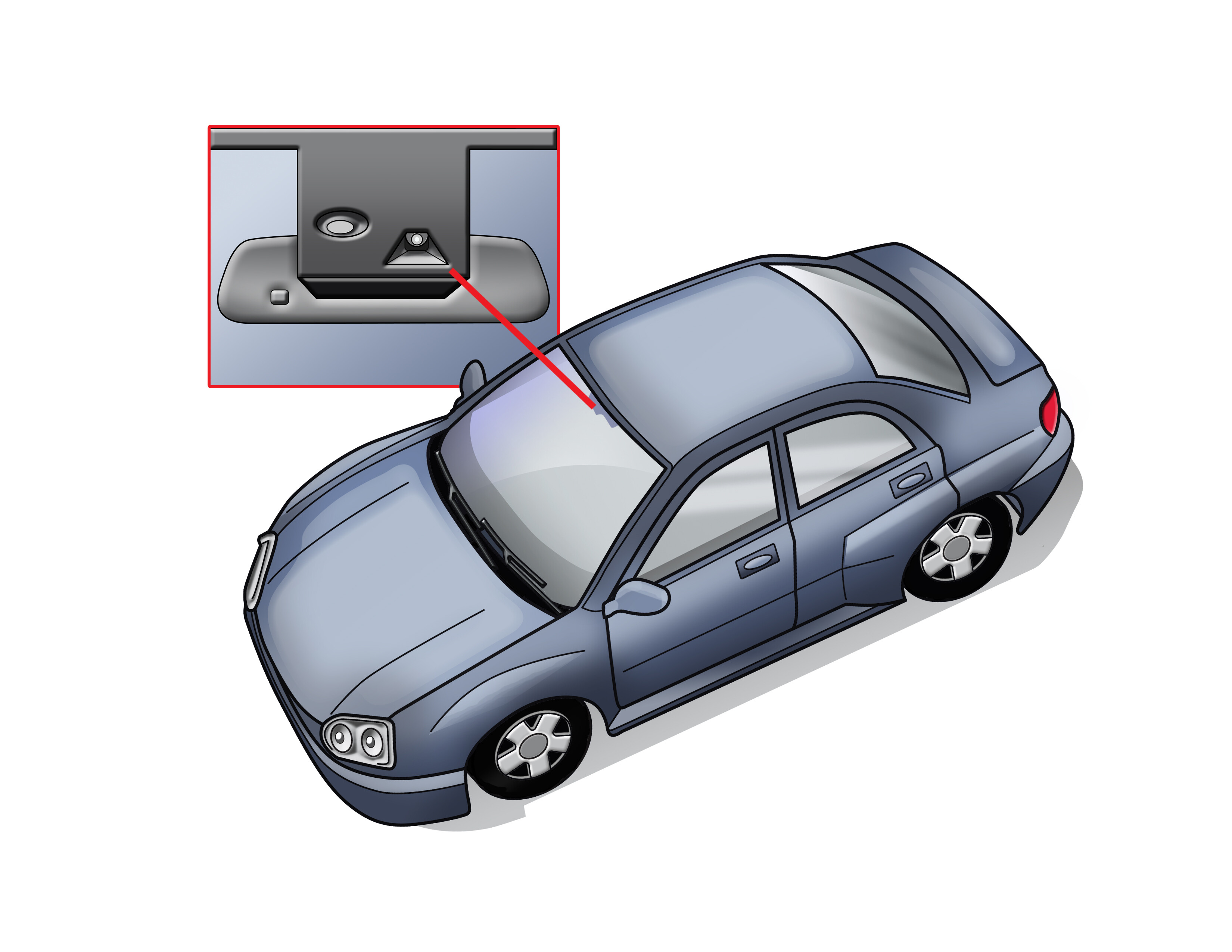 The
most common LDW system is a camera mounted high up in the windshield
(photo above), often as part of the rear view mirror mounting block. It
captures a moving view of the road ahead. The digitized image is parsed
for straight or dashed lines — the lane markings.
The
most common LDW system is a camera mounted high up in the windshield
(photo above), often as part of the rear view mirror mounting block. It
captures a moving view of the road ahead. The digitized image is parsed
for straight or dashed lines — the lane markings.
As the car deviates and approaches or reaches the lane marking, the driver gets a warning: a visual alert plus either an audible tone, a vibration in the steering wheel, or a vibration in the seat. If the turn signal is on, the car assumes the driver is intentionally crossing over the lane, and there’s no alert. That’s lane departure warning.
Sometimes
the steering change is effected by braking the opposite front wheel and
the car pivots back into the lane. The car can also move the car back
by turning the steering wheel. In either case, the driver can easily
overcome the car’s intentions by turning the wheel.
Laser radar to Measure Vehicle Distance:


Laser radar utilizes a laser beam to determine the distance to the measuring object.
The pulse method is used more frequently in low priced, compact systems. the pulse method measures distances by calculating the reciprocating time of light pulses between the objects.
It can be expressed in the following formula of


III) Information Services:
This service offers many useful features to protect the car and get information for vehicle safety and ease of driving.
Rear parking assistance: The system can help drivers in getting a better idea about the objects or vehicles at the rear side. It can also facilitate to display the corresponding situation on the screen.
Navigation System: Automotive navigation system is used in IVI systems. This system uses satellite navigation technique to show a top view of the map and provide ease of navigation to drivers.
Vehicle-related Information: This system gives an overall information about the vehicle including:
- Fuel level
- Total distance covered
- Brake fuel level
- Air filter clogged with dust particles
- Door open or close
Lane departure warning system is a mechanism designed to warn a driver when the vehicle begins to move out of its lane (unless a turn signal is on in that direction) on freeways and arterial roads.
Adaptive cruise control pacing the car against the car in front, lane departure warning or lane keep assist watching ahead and to the side.
Lane departure warning. It is a warning only. When the car drift near, onto, or over the lane marking, the car alerts the driver. The drive has to take corrective action by steering the car back to the middle of the lane. It doesn’t work if the road has no lane markings or lane markings are faded. If it’s raining or snowing, the camera may have trouble, too. By design, the lane departure warning system doesn’t alert, if turn signal is on, or (some cars) if when brakes are applied.
Lane Centering Assist (LCA) - This is the most invasive form of the technology. Rather than providing a warning, or kicking in only when the vehicle drifts toward the edge of its lane, this type of system is actually capable of keeping a vehicle centered in its lane at all times.
As the car deviates and approaches or reaches the lane marking, the driver gets a warning: a visual alert plus either an audible tone, a vibration in the steering wheel, or a vibration in the seat. If the turn signal is on, the car assumes the driver is intentionally crossing over the lane, and there’s no alert. That’s lane departure warning.
Laser radar to Measure Vehicle Distance:
Laser radar utilizes a laser beam to determine the distance to the measuring object.
The pulse method is used more frequently in low priced, compact systems. the pulse method measures distances by calculating the reciprocating time of light pulses between the objects.
It can be expressed in the following formula of
R = C *Τ/2
where C represents the speed of light,
Τ represents the reciprocating time and
R represents the distance.
Τ represents the reciprocating time and
R represents the distance.
Very Valuable Content
ReplyDeleteBest Security Agency In Mumbai
Good Information about car security system
ReplyDeleteThanks for writing such a good article, I stumbled onto your blog and read a few post. I like your style of writing... Caterpillar Communication Adapter
ReplyDeleteThanks for sharing such an informative blog!!! As, Auto Mirror Guard provides guards protect mirrors from theft We make anti theft side view mirror guards for all automobiles. Side View Mirror is also known by many names such as the fender, wing, and door mirror, of course all describing the essential driving aid. If you want to know more about Side View Mirror Theft Protection then visit to our website and in case of any query contact us now.
ReplyDeleteUVSS system is the best that you have got. There are no options better than under vehicle surveillance system. In case you are in serious need of complete security then go for UVSS without any hesitation.
ReplyDeleteUnder Vehicle Surveillance System
UVSS
UVSS System
Under Vehicle Surveillance System Manufacturer
Thanks for sharing this informative blog. It was really good. If you are looking for Anti Theft Mirror Guard then contact Auto Mirror Guard. We have Anti-theft guards available for all makes, models and years which are designed to protect your auto door mirrors from theft. Mirror guards are available for cars, trucks, and SUVs, made with carbon steel, powder coated, for more visit our site
ReplyDeleteThanks for sharing this post! It's very helpful for all. Auto mirror Guards are designed to mirror guards to protect your auto door mirrors from theft. They have Side View Mirror Theft Protection for cars, trucks, and SUVs, made with carbon steel, powder coated, we have guards available for all makes, models and years.
ReplyDeleteHere is coupon code for $20.00 OFF
ReplyDelete"Protection21" save at AutoMirrorGuard.com
I’d must talk to you here. Which is not some thing Which i do! I like reading an article that can make people believe. Also, thank you for permitting me to comment! private residential security
ReplyDelete